00195679-02_AI_XPS_DE+EN.pdf - 第96页
7 Interface Description Assembly Instructions 7.2 SIEMENS Interface Definition SIPLAC E X-Series Productivity Shuttle T ype I/II 38 7.2 SIEMENS Interface Definition If the device is equipped with an interf ace accord ing…
37
Assembly Instructions 7 Interface Description
SIPLACE X-Series Productivity Shuttle Type I/II 7.1 SMEMA Interface Definition
7 Interface Description
An interface between adjacent devices is necessary for handover and takeover. Our devices can
be equipped with different interfaces. If a change to different interface is made, this must be
carried out both on the interface module as well as on the control unit using the appropriate menu
command. We will be happy to provide information regarding problem areas due to changes to
the interface.
7.1 SMEMA Interface Definition
If the device is equipped with an interface according to the SMEMA definition, the connection is
made via a 16-pin socket connector and a 14-pin AMP connector.
The SMEMA interface definition specifies isolated contacts for the signals.
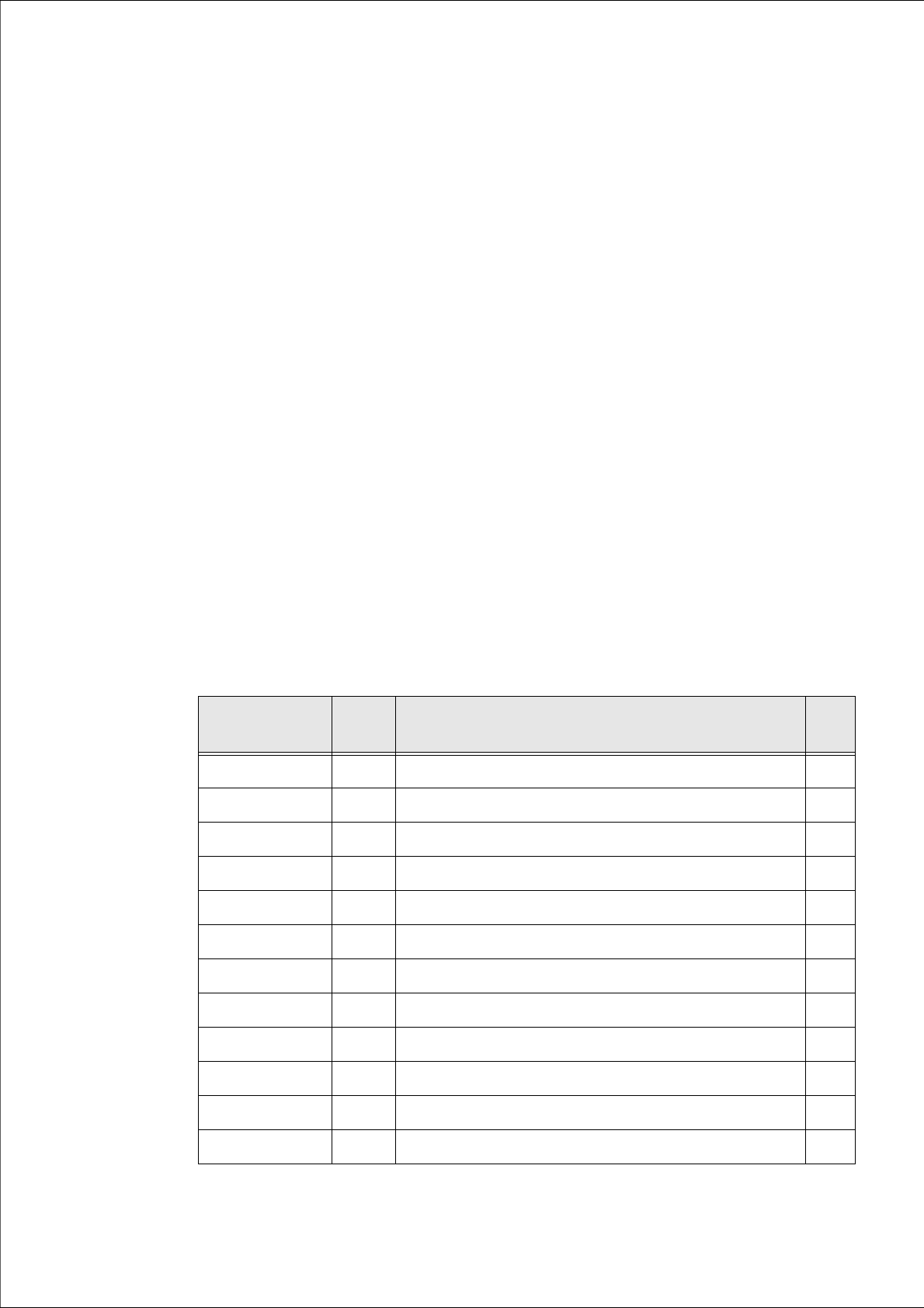
7.1.1 Pin Assignment
The circuit diagram for the system is applicable in each case.
Socket
connector
Color Signal designation AMP
1 WH N.C. 11
2 BN N.C. 12
3 GN + Board available 3
4 YE - Board available 4
5 GY + Not busy 1
6 PK - Not busy 2
7 BU + Pass 7
8 RD - Pass 8
13 BK Error loop 9
14 VT Error loop 10
15 GYPK + 24 V 13
16 RDBU GND 14
Table 7.1 - 1 SMEMA - Pin Assignment
7 Interface Description Assembly Instructions
7.2 SIEMENS Interface Definition SIPLACE X-Series Productivity Shuttle Type I/II
38
7.2 SIEMENS Interface Definition
If the device is equipped with an interface according to the Siemens definition, the connection is
made via a 20-pin socket connector and a 37-pin AMP connector.
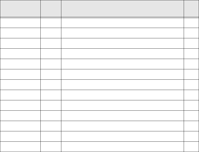
7.2.1 Pin Assignment
The circuit diagram for the system is applicable in each case.
Socket
connector
Color Signal designation AMP
2 WH N-1 GND 4
3 BN N-1 24 V 7
5 GN N+1 GND 11
6 YE N+1 24 V 14
11 BU Error loop 28
12 RD Error loop 29
13 BK GND (N+1, N-1) 30
14 VT Receival 31
15 GYPK Permission 32
17 GY Pass 34
18 RDBU Delivery 35
19 WHGN Requirement 36
20 BNGN GND (N+1, N-1) 37
Table 7.2 - 2 Siemens - Pin Assignment
39
Assembly Instructions 7 Interface Description
SIPLACE X-Series Productivity Shuttle Type I/II 7.3 AMI Interface Module
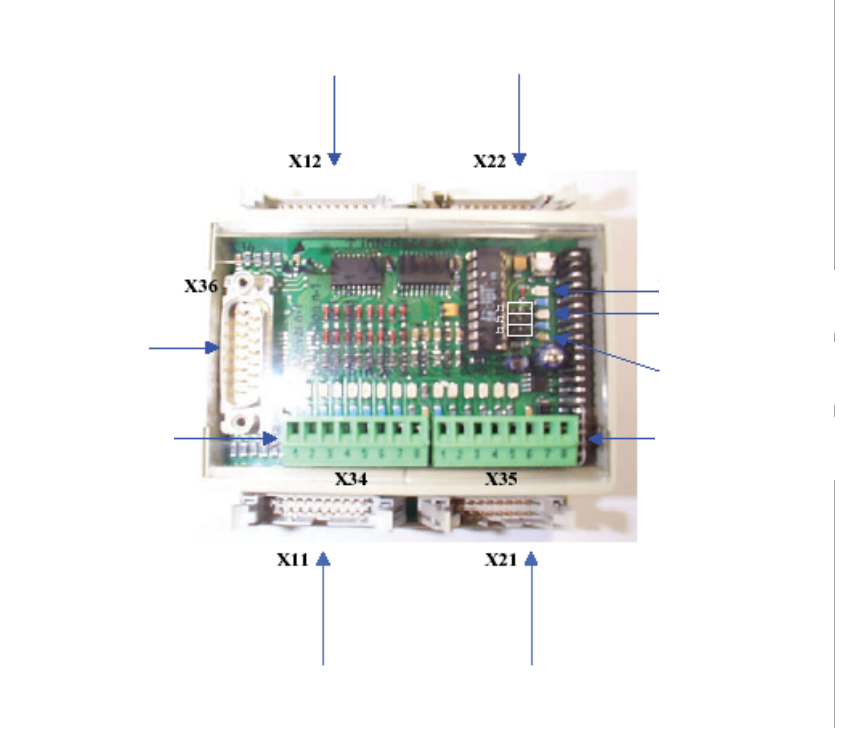
7.3 AMI Interface Module
The AMI module is used to connect the interfaces of the XPS to the SIPLACE placement system.
7.3.1 Connection Diagram
Figure 7 - 1 Interface Module AMI 3.x
SNEMA and
SMPI n+1
Siemens
n+1
ERROR
operating voltage
Addressing
PLC output with
status display
ELREST – PLC
parallel bus
PLC input
with status display
Siemens
n+1
SNEMA and
SMPI n+1