00195679-02_AI_XPS_DE+EN.pdf - 第97页
39 Assembly Instructions 7 Interface Description SIPLACE X-Series Productivity Shuttl e T ype I/II 7.3 AMI Interface Module 7.3 AMI Interface Module The AMI module is used to connect the interfaces of the XPS to the SIPL…

7 Interface Description Assembly Instructions
7.2 SIEMENS Interface Definition SIPLACE X-Series Productivity Shuttle Type I/II
38
7.2 SIEMENS Interface Definition
If the device is equipped with an interface according to the Siemens definition, the connection is
made via a 20-pin socket connector and a 37-pin AMP connector.
7.2.1 Pin Assignment
The circuit diagram for the system is applicable in each case.
Socket
connector
Color Signal designation AMP
2 WH N-1 GND 4
3 BN N-1 24 V 7
5 GN N+1 GND 11
6 YE N+1 24 V 14
11 BU Error loop 28
12 RD Error loop 29
13 BK GND (N+1, N-1) 30
14 VT Receival 31
15 GYPK Permission 32
17 GY Pass 34
18 RDBU Delivery 35
19 WHGN Requirement 36
20 BNGN GND (N+1, N-1) 37
Table 7.2 - 2 Siemens - Pin Assignment
39
Assembly Instructions 7 Interface Description
SIPLACE X-Series Productivity Shuttle Type I/II 7.3 AMI Interface Module
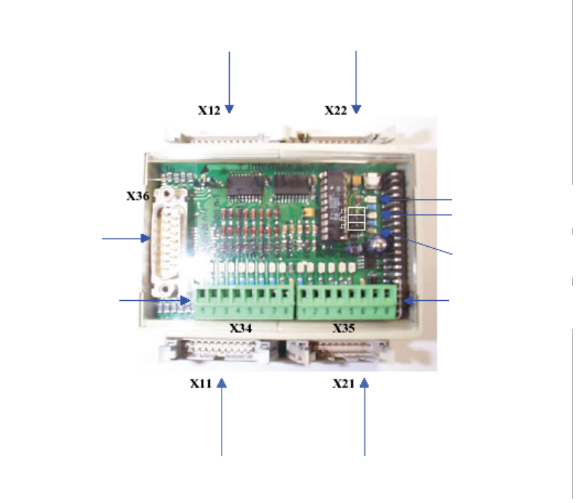
7.3 AMI Interface Module
The AMI module is used to connect the interfaces of the XPS to the SIPLACE placement system.
7.3.1 Connection Diagram
Figure 7 - 1 Interface Module AMI 3.x
SNEMA and
SMPI n+1
Siemens
n+1
ERROR
operating voltage
Addressing
PLC output with
status display
ELREST – PLC
parallel bus
PLC input
with status display
Siemens
n+1
SNEMA and
SMPI n+1
7 Interface Description Assembly Instructions
7.3 AMI Interface Module SIPLACE X-Series Productivity Shuttle Type I/II
40
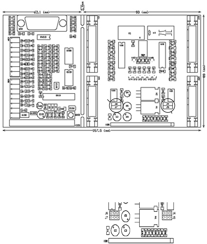
Figure 7 - 2 Dimension Drawing - AMI 3.0
7.3.2 Jumpers
Jumpers J4, J5, J6, and J7 must be inserted in the interface module on the rear printed-circuit
board for various interface definitions. For this purpose, the interface module must be opened, as
described in Chapter
7.3.3.
Figure 7 - 3 Jumpers
7.3.2.1 Siemens Interface
No jumpers have to be inserted, X11 + X12 are assigned all signals.
7.3.2.2 SMEMA Interface
No jumpers have to be inserted, X21 + X22 are assigned all signals.
Jumper J6
Jumper J7
Jumper J4
Jumper J5
J4 24 V
J5 GND
J6 24 V
}
}
N+1 via X22
N-1 via X21