00195679-02_AI_XPS_DE+EN.pdf - 第99页
41 Assembly Instructions 7 Interface Description SIPLACE X-Series Productivity Shuttl e T ype I/II 7.3 AMI Interface Module 7.3.3 Opening the Interface Module In order to set jumpers, the interfac e module must be opened…
7 Interface Description Assembly Instructions
7.3 AMI Interface Module SIPLACE X-Series Productivity Shuttle Type I/II
40
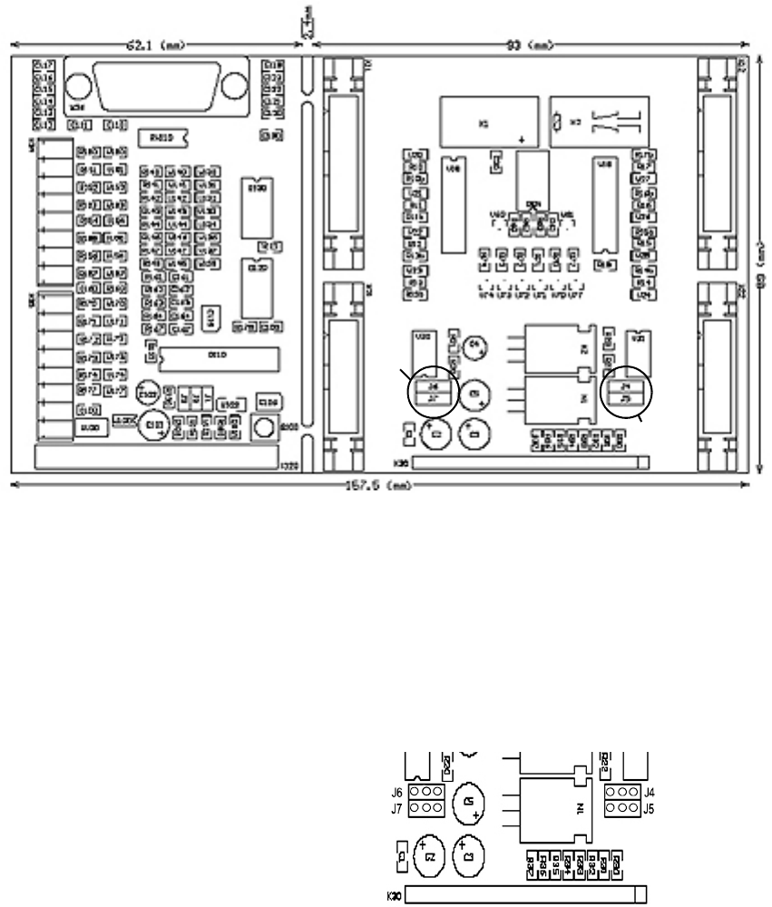
Figure 7 - 2 Dimension Drawing - AMI 3.0
7.3.2 Jumpers
Jumpers J4, J5, J6, and J7 must be inserted in the interface module on the rear printed-circuit
board for various interface definitions. For this purpose, the interface module must be opened, as
described in Chapter
7.3.3.
Figure 7 - 3 Jumpers
7.3.2.1 Siemens Interface
No jumpers have to be inserted, X11 + X12 are assigned all signals.
7.3.2.2 SMEMA Interface
No jumpers have to be inserted, X21 + X22 are assigned all signals.
Jumper J6
Jumper J7
Jumper J4
Jumper J5
J4 24 V
J5 GND
J6 24 V
}
}
N+1 via X22
N-1 via X21
41
Assembly Instructions 7 Interface Description
SIPLACE X-Series Productivity Shuttle Type I/II 7.3 AMI Interface Module
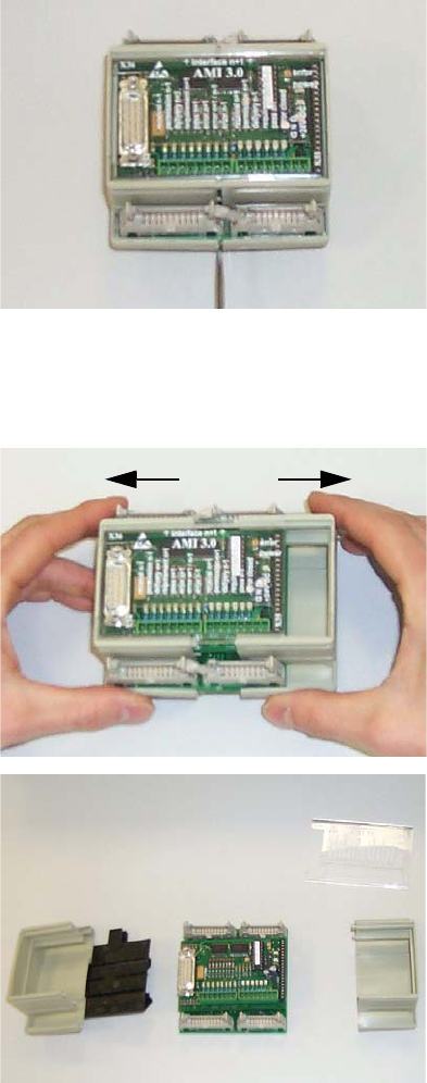
7.3.3 Opening the Interface Module
In order to set jumpers, the interface module must be opened as shown below.
1. Disconnect all connections from the interface module.
2. Remove the interface module from the bracket.
3. The housing is opened to the side. You can use a screwdriver to carefully open the fastener.
Figure 7 - 4 Opening the Interface Module - Figure 1
4. Pull the two parts of the housing towards the right and left.
Figure 7 - 5 Opening the Interface Module - Figures 2 and 3
7 Interface Description Assembly Instructions
7.3 AMI Interface Module SIPLACE X-Series Productivity Shuttle Type I/II
42
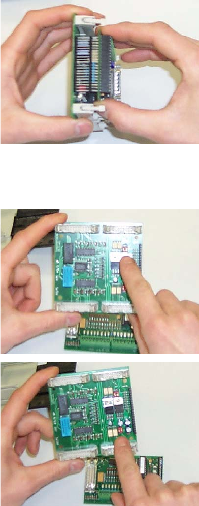
5. Remove the upper printed-circuit board carefully from the base.
Figure 7 - 6 Opening the Interface Module - Figure 4
6. You will find jumpers J4, J5, J6, and J7 on the lower printed-circuit board.
Figure 7 - 7 Opening the Interface Module - Figures 5 and 6
Reassemble the interface module in the reverse order.