00191185-01.pdf - 第17页
Feeder Fastening Attachment for Component Table (Optiona l) SIPLACE 80 S-20/F4/S-15/F3 Retrofitting Instructions Edition 05/98 Seit e 6 3 Prep aratory Step s 3.1 Preparat ory Steps for SIPLA CE 80 S- 20/F4/S-15 /F3 • T u…
Retrofitting Instructions Feeder Fastening Attachment (Addition) for Component Table SIPLACE 80 S-20/F4/S-15/F3
Edition 05/98
Seite 5
DANGER
O O O
The machines in the SIPLACE family are powered by 3 x 400 V +/- 10%, 50/60 Hz line voltage.
Portions of the system are therefore conducting dangerous electricity. This voltage is applied to specific
modules inside the machine even while the master switch is turned off!
Unprofessional handling of the machines or contact with portions there of conducting electricity may result in
death, serious injury or considerable material damage.
At all times, observe applicable accident prevention regulations and VDE codes / regulations of the society of
electrical engineers and the special safety regulations in your country. More stringent safety regulations to
VDE 0113 or the corresponding instructions in your country must be adhered to during all work in the
machine.
Only Siemens service engineers
are permitted to carry out these retrofit jobs.
Before starting the retrofitting, turn off the master switch and pull out the mains plug. Secure the machine to
prevent it from being restarted by unauthorized personnel.
2.1 Definitions
DANGER O O O
As used in these instructions, this means that death, serious injury or extensive material damage will occur if
the instructions regarding danger are not observed.
WARNING
O O
As used in these instructions, this means that death, serious injury or extensive material damage may occur if
the instructions in the warnings are not observed.
CAUTION
O
As used in these instructions, this means that minor injury or material damage may occur if the instructions in
the caution message are not observed.
NOTE
As used in these instructions, this means that particular attention is to be directed to important information
regarding the product or the specific part of the instructions.

Feeder Fastening Attachment for Component Table (Optional) SIPLACE 80 S-20/F4/S-15/F3 Retrofitting Instructions
Edition 05/98
Seite 6
3 Preparatory Steps
3.1 Preparatory Steps for SIPLACE 80 S-20/F4/S-15/F3
• Turn the placers off at the master switched and pull out the mains plug.
• Tear down the two component tables.
•
Disconnect the electrical connections of the two component tables.
•
Loosen the horizontal tensioners on the two component tables and move the tables out of the placer
3.2 Preparatory Steps for SIPLACE 80 F4/F3 with WPC
• Turn the placer off at the master switch and pull out the mains plug.
• Tear down the two component tables.
• Disconnect the electrical connections of the two component tables and the WPC
• Pull the WPC out of the placer.
• Loosen the horizontal tensioners on the left-hand component table and move it out of the placer.
• Loosen the two component table fastening screws on the right-hand side.
• Lift the component table out of the placer and place on a suitable stable surface (e.g., lab cart).
WARNING
O O
You will require the assistance of a second person to lift the component table. It is heavy and the risk of
injury is high.
Retrofitting Instructions Feeder Fastening Attachment (Addition) for Component Table SIPLACE 80 S-20/F4/S-15/F3
Edition 05/98
Seite 7
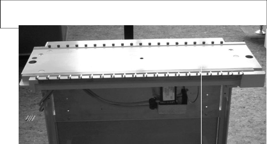
4 Mounting the Feeder Fastening Attachment
• Mount the drilling jig on the component table (see Fig. 1).
•
Using a 3.3 mm drill, drill the 5 holes required.
•
Use a M4 tap to cut the 5 threads required.
•
Fasten the to the component table with the M4 x 4 socket head cap screws in the retrofitting kit
(see Fig. 2).
5 Final Steps
5.1 SIPLACE 80 S-20/F4/S-15/F3
•
Move the two component tables into the placer.
•
Fasten the component tables in place with the horizontal tensioners.
•
Make all electrical connections.
•
Set up the component tables once again
5.2 SIPLACE 80 F4/F3 with WPC
•
With the assistance of a second person, lift the component table on the right-hand side into the placer.
WARNING O O
You will require the assistance of the second person to lift the component table. It is heavy and the risk of
injury is high.
• Using the two socket head cap screws, fasten the component table in place.
• Move the WPC into the placer.
• Move the component table on the left-hand side into the placer.
• Fasten the component table in place with the horizontal tensioners.
•
Make all the electrical connections.
•
Set up the component tables once again.