00191185-01.pdf - 第18页
Retrofitting Instructions Feeder Fastening Attachment (Addition) for Component Tab le SIP LACE 80 S-20/F4/S-15/F3 Edition 05/98 Seite 7 4 Moun ting the Feeder Fasten ing A tt achment • Mo unt the drilling jig on the comp…

Feeder Fastening Attachment for Component Table (Optional) SIPLACE 80 S-20/F4/S-15/F3 Retrofitting Instructions
Edition 05/98
Seite 6
3 Preparatory Steps
3.1 Preparatory Steps for SIPLACE 80 S-20/F4/S-15/F3
• Turn the placers off at the master switched and pull out the mains plug.
• Tear down the two component tables.
•
Disconnect the electrical connections of the two component tables.
•
Loosen the horizontal tensioners on the two component tables and move the tables out of the placer
3.2 Preparatory Steps for SIPLACE 80 F4/F3 with WPC
• Turn the placer off at the master switch and pull out the mains plug.
• Tear down the two component tables.
• Disconnect the electrical connections of the two component tables and the WPC
• Pull the WPC out of the placer.
• Loosen the horizontal tensioners on the left-hand component table and move it out of the placer.
• Loosen the two component table fastening screws on the right-hand side.
• Lift the component table out of the placer and place on a suitable stable surface (e.g., lab cart).
WARNING
O O
You will require the assistance of a second person to lift the component table. It is heavy and the risk of
injury is high.
Retrofitting Instructions Feeder Fastening Attachment (Addition) for Component Table SIPLACE 80 S-20/F4/S-15/F3
Edition 05/98
Seite 7
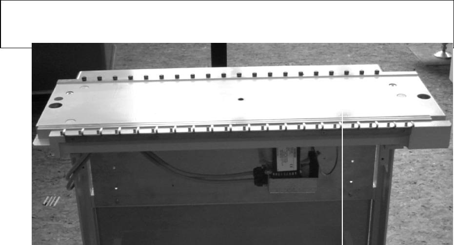
4 Mounting the Feeder Fastening Attachment
• Mount the drilling jig on the component table (see Fig. 1).
•
Using a 3.3 mm drill, drill the 5 holes required.
•
Use a M4 tap to cut the 5 threads required.
•
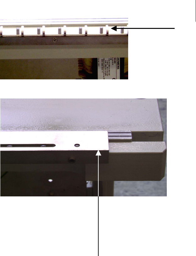
Fasten the to the component table with the M4 x 4 socket head cap screws in the retrofitting kit
(see Fig. 2).
5 Final Steps
5.1 SIPLACE 80 S-20/F4/S-15/F3
•
Move the two component tables into the placer.
•
Fasten the component tables in place with the horizontal tensioners.
•
Make all electrical connections.
•
Set up the component tables once again
5.2 SIPLACE 80 F4/F3 with WPC
•
With the assistance of a second person, lift the component table on the right-hand side into the placer.
WARNING O O
You will require the assistance of the second person to lift the component table. It is heavy and the risk of
injury is high.
• Using the two socket head cap screws, fasten the component table in place.
• Move the WPC into the placer.
• Move the component table on the left-hand side into the placer.
• Fasten the component table in place with the horizontal tensioners.
•
Make all the electrical connections.
•
Set up the component tables once again.
Feeder Fastening Attachment for Component Table (Optional) SIPLACE 80 S-20/F4/S-15/F3 Retrofitting Instructions
Edition 05/98
Seite 8
Feeder fastening
attachment
Fig. 2 a
Fig. 1 a
Fig. 1 b