00195760-0102_UM_D3_SR605_EN.pdf - 第116页
3 Technical data for the machine User Manual SIPLACE D3 3.5 Placement head From software version SR.605.xx 07/2008 EN Edition 116 3.5.3.1 Description This sophisticated placement head consists of tw o pla cement heads of…
User Manual SIPLACE D3 3 Technical data for the machine
From software version SR.605.xx 07/2008 EN Edition 3.5 Placement head
115
3.5.3 SIPLACE TwinHead for high-precision IC placement
3
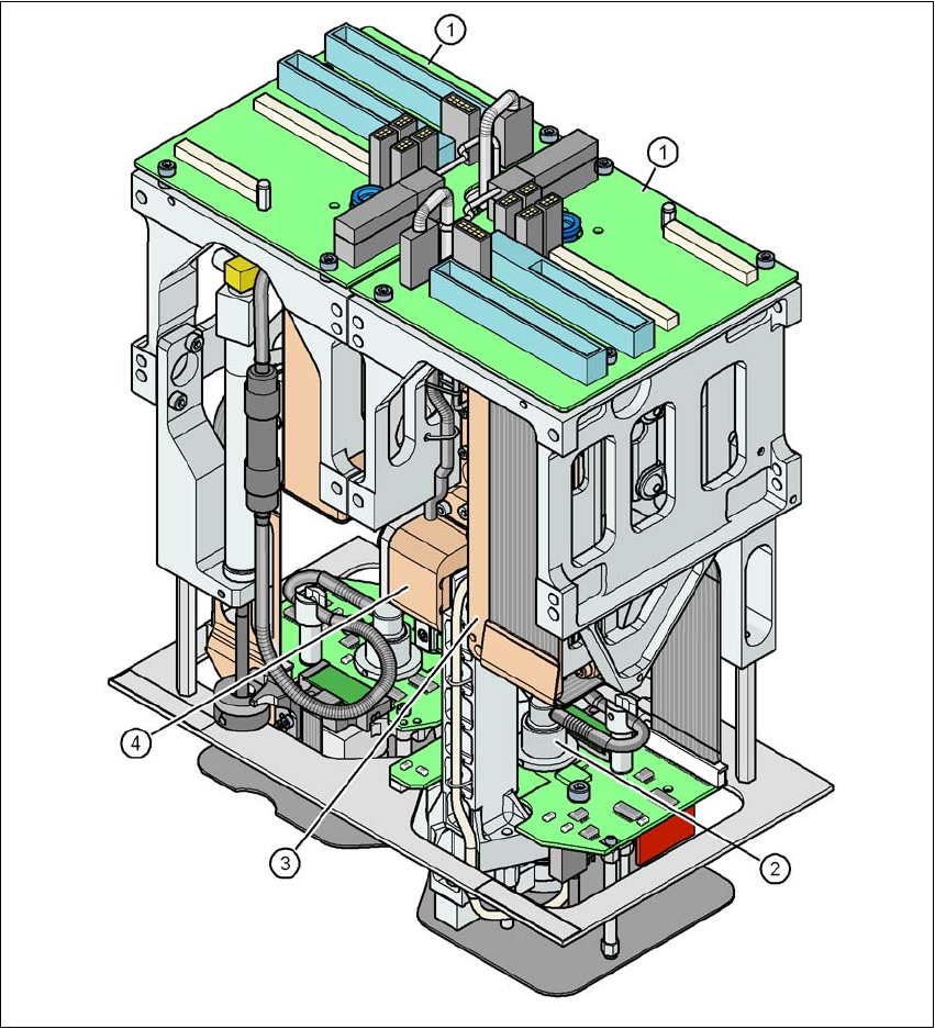
Fig. 3.5 - 5 TwinHead for high-precision IC placement
3
(1) Pick&Place module - the TwinHead consists of 2 Pick&Place modules (P&P1 and P&P2)
(2) DP axis
(3) Z axis drive
(4) Incremental distance measuring system for the Z axis
3 Technical data for the machine User Manual SIPLACE D3
3.5 Placement head From software version SR.605.xx 07/2008 EN Edition
116
3.5.3.1 Description
This sophisticated placement head consists of two placement heads of the same type coupled to-
gether (twin head). Both heads work using the Pick&Place principle. The TwinHead is suitable for
processing particularly difficult or large components. Two components are picked up by the place-
ment head, optically centered on the way to the placement position and rotated into the necessary
placement angle. They are then placed gently and accurately onto the PCB with a controlled blast
of air.
New nozzles (type 5xx) have been developed for the TwinHead. It is also possible to fit an adapter
and then use type 4 nozzles for the Pick&Place head and type 8xx and 9xx nozzles for the Col-
lect&Place heads.
3.5.3.2 Technical data
Optical centering with Stationary P&P component camera,
(type 33) 55 x 45, digital
(see Section 3.8.5
, page 137)
Stationary P&P component camera,
(type 25) 16 x 16, digital
(see Section 6.6, page 315)
Range of components
a
0402 to SO, PLCC, QFP, BGA, spe-
cial components, bare dies, flip-
chips
0201 to SO, PLCC, QFP, sockets,
plugs, BGA, special components,
bare dies, flip-chips, shields
Component specification
b
max. height
min. lead pitch
min. lead width
min. ball pitch
min. ball diameter
min. dimensions
max. dimensions
max. weight
c
25 mm (higher available on request)
0.3 mm
0.15 mm
0.35 mm
0.2 mm
1.0 x 0.5 mm²
55 x 45 mm² (single measurement)
For use with two nozzles
50 x 50 mm² or
69 x 10 mm²
For use with one nozzle
85 x 85 mm² or
125 x 10 mm²
max. 200 x 125 mm² (with restric-
tions)
100 g
25 mm (higher available on request)
0.25 mm
0.1 mm
0.14 mm
0.08 mm
0.6 x 0.3 mm²
16 x 16 mm² (single measurement)
100 g

User Manual SIPLACE D3 3 Technical data for the machine
From software version SR.605.xx 07/2008 EN Edition 3.5 Placement head
117
Programmable set-down
force
1.0 N - 15 N
2.0 N - 30 N
d
1.0 N - 15 N
2.0 N - 30 N
d
Nozzle types 5xx (standard)
4xx + adapter
8xx + adapter
9xx + adapter
gripper
5xx (standard)
4xx + adapter
8xx + adapter
9xx + adapter
gripper
Nozzle spacing on the
two Pick&Place heads
70.8 mm 70.8 mm
X/Y accuracy
e
± 26 μm / 3σ, ± 35 μm / 4σ ± 22 μm / 3σ, ± 30 μm / 4σ
Angular accuracy ± 0.05° / 3 σ, ± 0.07° / 4 σ ± 0.05° / 3 σ, ± 0.07° / 4 σ
CO camera type 33 25
Illumination level 6 6
Possible illumination level
settings
256
6
256
6
a) Please note that the component range that can be placed is also affected by the pad geometry, the cus-
tomer-specific standards and the packaging tolerances.
b) If the C&P head and TwinHead are combined in a placement area, the maximum dimensions are restricted.
c) If standard nozzles are used
d) SIPLACE High-Force Head, Section 6.5
, page 314.
e) The accuracy value was measured using the vendor-neutral IPC standard.