00195760-0102_UM_D3_SR605_EN.pdf - 第123页
User Manual SIPLACE D3 3 Technical data for the machine From software version SR.605.xx 07/2008 EN Edition 3.7 PCB conveyor system 123 3.7 PCB conveyor system The machine is supplied with a single PCB conveyor as standar…

3 Technical data for the machine User Manual SIPLACE D3
3.6 Gantry system From software version SR.605.xx 07/2008 EN Edition
122
The Y axis essentially consists of the following main modules:
– Y-axis linear motor (primary part) (item 1 in Fig. 3.6 - 3
, page 121)
– Permanent magnet (secondary part of the Y-axis linear motor) (item 2 in Fig. 3.6 - 3
, page
121
)
– Linear distance measuring system (item 3 in Fig. 3.6 - 3
, page 121)
– Guide system (item 4 in Fig. 3.6 - 3
, page 121)
– Cable and hose carrier (item 5 in Fig. 3.6 - 3
, page 121)
The Y axis is driven by a linear motor. The secondary part of the drive is made up of permanent
magnets and is mounted on the machine frame. The primary part is bolted to the gantry.
3.6.5 Technical data for the Y axis
Drive Direct, linear motor
Maximum speed 2.5 m/sec.
Traversing path 1430 mm
Distance measuring system Metal linear scale
Scale length 1850 mm
Resolution 1 μm
User Manual SIPLACE D3 3 Technical data for the machine
From software version SR.605.xx 07/2008 EN Edition 3.7 PCB conveyor system
123
3.7 PCB conveyor system
The machine is supplied with a single PCB conveyor as standard. The PCB dual conveyor is avail-
able as an option from the factory (see Section 3.7.1.2
, page 124). The left or the right side of the
PCB conveyor can be used as the stationary side, as required.
The conveyor belts are driven by DC motors. There is a lifting table for clamping the PCBs in each
processing area. The PCB conveyor width can either be set from the user interface or preset in
the placement program.
3.7.1 Structure
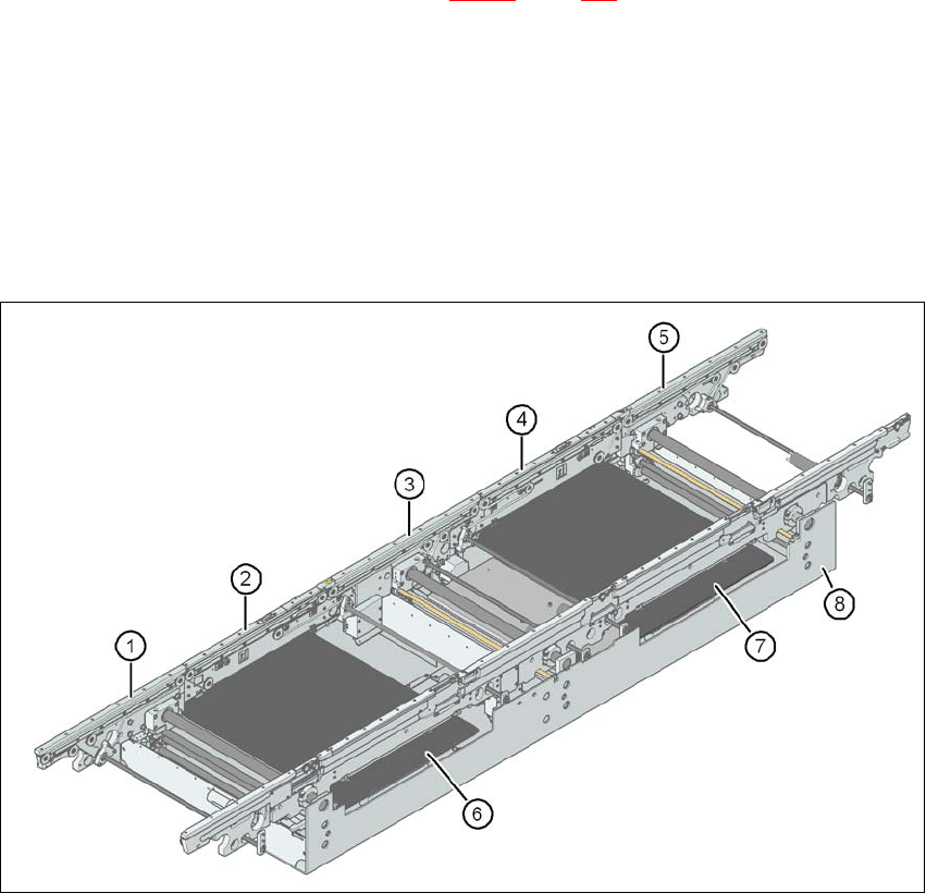
3.7.1.1 Structure of the PCB single conveyor
3
Fig. 3.7 - 1 Structure of the PCB single conveyor
(1) Input conveyor
(2) Processing conveyor 1
(3) Intermediate conveyor
(4) Processing conveyor 2
(5) Output conveyor
(6) Lifting table 1
(7) Lifting table 2
(8) Assembly tray
3 Technical data for the machine User Manual SIPLACE D3
3.7 PCB conveyor system From software version SR.605.xx 07/2008 EN Edition
124
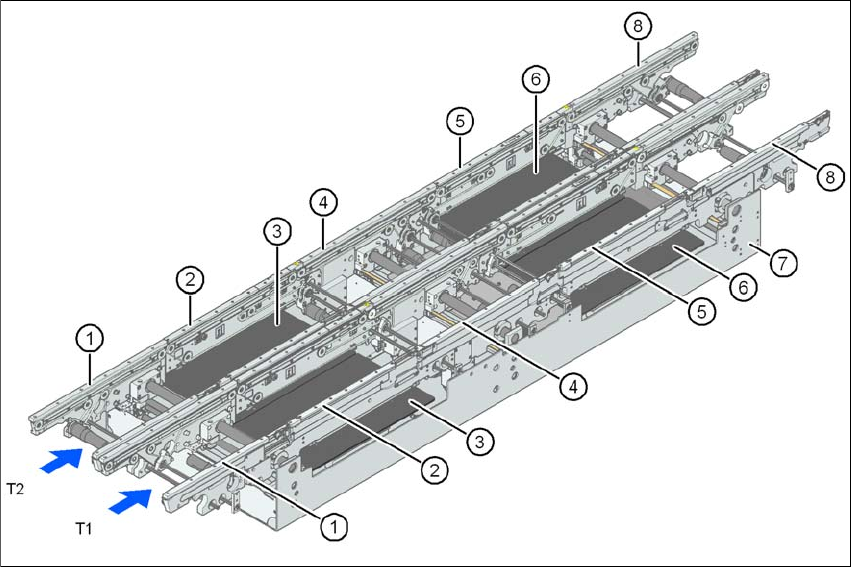
3.7.1.2 Structure of the flexible PCB dual conveyor
The flexible dual conveyor has two conveyor tracks that are electrically and mechanically inde-
pendent of one another.
3
Fig. 3.7 - 2 Structure of the PCB dual conveyor
(1) Input conveyor
(2) Processing conveyor 1
(3) Lifting table 1
(4) Intermediate conveyor
(5) Processing conveyor 2
(6) Lifting table 2
(7) Assembly tray
(8) Output conveyor
T1 Conveyor track 1
T2 Conveyor track 2
3.7.2 Description
For placement, the PCB is clamped from below. The distance between the top of the PCB and the
placement head thus remains unchanged for each PCB, and is not dependent on the thickness of