00195760-0102_UM_D3_SR605_EN.pdf - 第131页
User Manual SIPLACE D3 3 Technical data for the machine From software version SR.605.xx 07/2008 EN Edition 3.7 PCB conveyor system 131 3.7.7 Definition of the PCB warpage 3.7.7.1 PCB warp age on the conveyor PCB warpage …

3 Technical data for the machine User Manual SIPLACE D3
3.7 PCB conveyor system From software version SR.605.xx 07/2008 EN Edition
130
3.7.6 Configuration options
3.7.6.1 PCB single conveyor
Item no. 00119625-xx D3 modular single conveyor
Item no. 00119626-xx Stationary conveyor side on the right, HF/X/D-series
Item no. 00119628-xx Stationary conveyor side on the left, HF/X/D-series
Item no. 00119629-xx Conveyor width 250/508 mm (Wide board), X-series/D3
Item no. 00119631-xx Conveyor width 242/508 mm (Wide board), D1/D2/D3/D4
3.7.6.2 Flexible PCB dual conveyor
Item no. 00119627-xx D3 modular dual conveyor
Item no. 00119626-xx Stationary conveyor side on the right, HF/X/D-series
Item no. 00119628-xx Stationary conveyor side on the left, HF/X/D-series
Item no. 00119629-xx Conveyor width 250/508 mm (Wide board), X-series/D3
Item no. 00119631-xx Conveyor width 242/508 mm (Wide board), D1/D2/D3/D4
Clearance on PCB underside
Standard
Option
25 mm ± 0.2 mm
max. 40 mm ± 0.2 mm
PCB conveyor height 830mm ± 15mm (standard)
900mm ± 15mm (optional)
930mm ± 15mm (optional)
950mm ± 15mm (SMEMA: optional)
Type of interface SMEMA / Siemens
Component-free PCB handling edge 3 mm
PCB changeover time < 2.5 s
PCB positioning accuracy ± 0.5 mm
Conveyor mode synchronous or asynchronous (selected via the soft-
ware)
Components on each conveyor same or different
PCB width on each conveyor same or different
Bad fiducial detection synchronous: possible, no global ink spot
asynchronous: possible
Automatic width adjustment synchronous: possible, asynchronous: possible
a) See Long board option, Section 6.11, page 327
User Manual SIPLACE D3 3 Technical data for the machine
From software version SR.605.xx 07/2008 EN Edition 3.7 PCB conveyor system
131
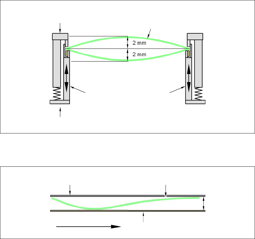
3.7.7 Definition of the PCB warpage
3.7.7.1 PCB warpage on the conveyor
PCB warpage across the direction of travel max. 1% of the PCB diagonal, but not exceeding 2 mm
3
PCB warpage in direction of travel + PCB thickness < 5.5 mm
3
3
Fixed clamped edge
Movable clamping device
Printed circuit board
Conveyor side wall
Fixed clamped edge
Conveyor belt
Printed circuit board
PCB transport direc-
tion
5.5 mm
3 Technical data for the machine User Manual SIPLACE D3
3.7 PCB conveyor system From software version SR.605.xx 07/2008 EN Edition
132
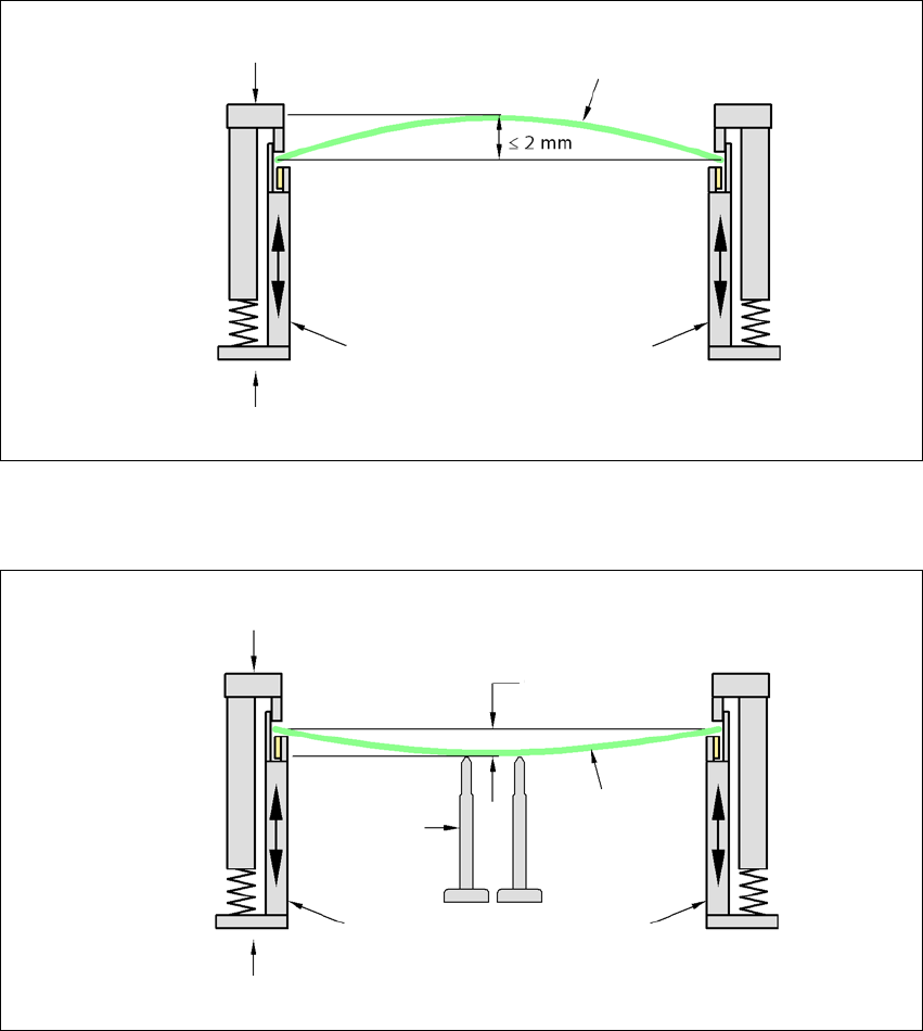
3.7.7.2 PCB warpage during placement
A warpage of 2 mm can lead to problems focussing on local fiducials and ink spots in the middle
of the PCB. The digital camera's focus is 2 mm. When all the tolerances are taken into account,
this value is reduced to 1.5 mm. Also note that the component height is reduced by the warpage.
3
3
PCB warpage down, max. 0.5 mm
3
→ Use magnetic pin supports to achieve this value.
Movable clamping device
Fixed clamped edge
Printed circuit board
Conveyor side wall
Printed circuit board
Magnetic pin
support
Movable clamping device
Fixed clamped edge
Conveyor side wall
0.5 mm