00195760-0102_UM_D3_SR605_EN.pdf - 第133页
User Manual SIPLACE D3 3 Technical data for the machine From software version SR.605.xx 07/2008 EN Edition 3.8 Vision system 133 3.8 V ision system 3.8.1 Structure A componen t camera is in tegrated into each Collect&…
3 Technical data for the machine User Manual SIPLACE D3
3.7 PCB conveyor system From software version SR.605.xx 07/2008 EN Edition
132
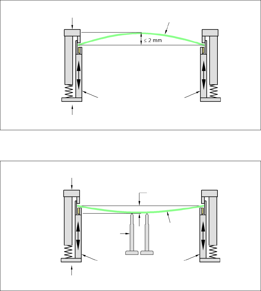
3.7.7.2 PCB warpage during placement
A warpage of 2 mm can lead to problems focussing on local fiducials and ink spots in the middle
of the PCB. The digital camera's focus is 2 mm. When all the tolerances are taken into account,
this value is reduced to 1.5 mm. Also note that the component height is reduced by the warpage.
3
3
PCB warpage down, max. 0.5 mm
3
→ Use magnetic pin supports to achieve this value.
Movable clamping device
Fixed clamped edge
Printed circuit board
Conveyor side wall
Printed circuit board
Magnetic pin
support
Movable clamping device
Fixed clamped edge
Conveyor side wall
0.5 mm

User Manual SIPLACE D3 3 Technical data for the machine
From software version SR.605.xx 07/2008 EN Edition 3.8 Vision system
133
3.8 Vision system
3.8.1 Structure
A component camera is integrated into each Collect&Place head (see Fig. 3.5 - 2 page 108 and
Fig. 3.5 - 4
page 112). The stationary P&P component vision camera (type 33) 55 x 45 digital for
the TwinHead is permanently fixed to the machine frame.
The component vision module is used to determine:
– the precise position of the components at the nozzle and
– the geometry of the package form.
The PCB vision module uses fiducials on the PCBs to determine:
– the position of the PCB,
– its rotation angle
– and the PCB skew.
The PCB cameras are fixed to the bottom of the gantries. They use fiducials on the feeder mod-
ules to determine the exact pick-up position of components, which is particularly important for
small components.
WARNING
RISK OF HEAD CRASH 3
When the placement head is changed from the TwinHead to the Collect&Place head, the Twin-
Head's stationary component vision camera, P&P (type 33) 55 x 45, and stationary P&P compo-
nent vision camera (type 25) 16 x 16 digital must be removed, otherwise the Collect&Place head
will collide with the camera housings.
3 Technical data for the machine User Manual SIPLACE D3
3.8 Vision system From software version SR.605.xx 07/2008 EN Edition
134
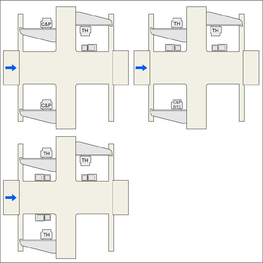
3.8.2 Assembly positions for the stationary cameras - IC and FC cameras
3
Fig. 3.8 - 1 IC and FC cameras on the machine
C&P C&P12 or C&P6
C&P6/12 6-segment Collect & Place head or 12-segment Collect & Place head
TH TwinHead
25 FC camera, type 25
33 IC camera, type 33
G1, G3, G4 Gantry 1, gantry 3, gantry 4
33 or 25
25 and 33
25 and 33 33 and 25 25 and 33
33 or 25
G3
G3
G4
G4
G1
G1
G4
G3
G1