00195760-0102_UM_D3_SR605_EN.pdf - 第134页
3 Technical data for the machine User Manual SIPLACE D3 3.8 Vision system From software ve rsion SR.605.xx 07/2008 EN Edition 134 3.8.2 Assembly positions for the stat ionary cameras - IC and FC cameras 3 Fig. 3.8 - 1 IC…

User Manual SIPLACE D3 3 Technical data for the machine
From software version SR.605.xx 07/2008 EN Edition 3.8 Vision system
133
3.8 Vision system
3.8.1 Structure
A component camera is integrated into each Collect&Place head (see Fig. 3.5 - 2 page 108 and
Fig. 3.5 - 4
page 112). The stationary P&P component vision camera (type 33) 55 x 45 digital for
the TwinHead is permanently fixed to the machine frame.
The component vision module is used to determine:
– the precise position of the components at the nozzle and
– the geometry of the package form.
The PCB vision module uses fiducials on the PCBs to determine:
– the position of the PCB,
– its rotation angle
– and the PCB skew.
The PCB cameras are fixed to the bottom of the gantries. They use fiducials on the feeder mod-
ules to determine the exact pick-up position of components, which is particularly important for
small components.
WARNING
RISK OF HEAD CRASH 3
When the placement head is changed from the TwinHead to the Collect&Place head, the Twin-
Head's stationary component vision camera, P&P (type 33) 55 x 45, and stationary P&P compo-
nent vision camera (type 25) 16 x 16 digital must be removed, otherwise the Collect&Place head
will collide with the camera housings.
3 Technical data for the machine User Manual SIPLACE D3
3.8 Vision system From software version SR.605.xx 07/2008 EN Edition
134
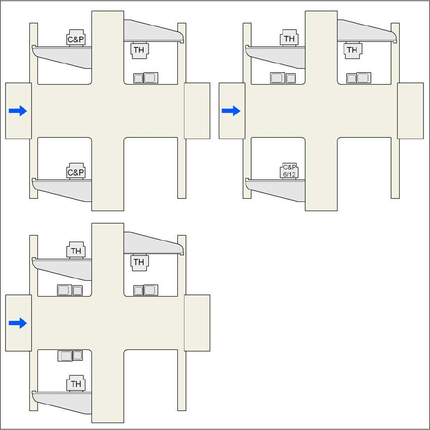
3.8.2 Assembly positions for the stationary cameras - IC and FC cameras
3
Fig. 3.8 - 1 IC and FC cameras on the machine
C&P C&P12 or C&P6
C&P6/12 6-segment Collect & Place head or 12-segment Collect & Place head
TH TwinHead
25 FC camera, type 25
33 IC camera, type 33
G1, G3, G4 Gantry 1, gantry 3, gantry 4
33 or 25
25 and 33
25 and 33 33 and 25 25 and 33
33 or 25
G3
G3
G4
G4
G1
G1
G4
G3
G1
User Manual SIPLACE D3 3 Technical data for the machine
From software version SR.605.xx 07/2008 EN Edition 3.8 Vision system
135
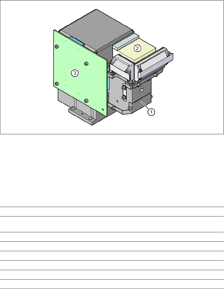
3.8.3 C&P component camera, type 28, 18 x 18, digital
3.8.3.1 Structure
3
Fig. 3.8 - 2 C&P component camera, type 28, 18 x 18, digital
3
(1) Component camera lens and illumination
(2) Camera amplifier
(3) Illumination control
3.8.3.2 Technical data
3
Component dimensions 0.5 x 0.5 mm² to 18.7 x 18.7 mm²
Range of components 0402 to PLCC44 incl. BGA, μBGA, flip-chip, TSOP, QFP,
SO to SO32, DRAM
Min. lead pitch 0.5 mm
Min. lead width 0.2 mm
Min. ball pitch 0.55 mm
Min. ball diameter 0.2 mm
Field of vision 24.5 x 24.5 mm²
Method of illumination Front-illumination (5 levels, programmable as required)