00195760-0102_UM_D3_SR605_EN.pdf - 第14页
Content User Manual SIPLACE D3 07/2008 EN Edition 14 6.9 Siemens interface . . . . . . . . . . . . . . . . . . . . . . . . . . . . . . . . . . . . . . . . . . . . . . . . . . . . . . . . . . . . . 326 6.10 Package for sp…
User Manual SIPLACE D3 Content
07/2008 EN Edition
13
6.2.4.2 Controls . . . . . . . . . . . . . . . . . . . . . . . . . . . . . . . . . . . . . . . . . . . . . . . . . . . . . . . . . 306
6.2.5 Dimensions of the machine with MTC . . . . . . . . . . . . . . . . . . . . . . . . . . . . . . . . . . 307
6.3 Waffle-pack changer . . . . . . . . . . . . . . . . . . . . . . . . . . . . . . . . . . . . . . . . . . . . . . . . . . . . . . . . . . . 308
6.3.1 Safety instructions . . . . . . . . . . . . . . . . . . . . . . . . . . . . . . . . . . . . . . . . . . . . . . . . . 308
6.3.2 Description . . . . . . . . . . . . . . . . . . . . . . . . . . . . . . . . . . . . . . . . . . . . . . . . . . . . . . . 308
6.3.3 Technical data . . . . . . . . . . . . . . . . . . . . . . . . . . . . . . . . . . . . . . . . . . . . . . . . . . . . 309
6.3.3.1 Dimensions, weight . . . . . . . . . . . . . . . . . . . . . . . . . . . . . . . . . . . . . . . . . . . . . . . . 309
6.3.3.2 Electrical ratings . . . . . . . . . . . . . . . . . . . . . . . . . . . . . . . . . . . . . . . . . . . . . . . . . . . 309
6.3.3.3 Noise emissions . . . . . . . . . . . . . . . . . . . . . . . . . . . . . . . . . . . . . . . . . . . . . . . . . . . 310
6.3.3.4 Permitted environmental factors. . . . . . . . . . . . . . . . . . . . . . . . . . . . . . . . . . . . . . . 310
6.3.4 Installation notes for the WPC . . . . . . . . . . . . . . . . . . . . . . . . . . . . . . . . . . . . . . . . 310
6.3.5 Dimensions . . . . . . . . . . . . . . . . . . . . . . . . . . . . . . . . . . . . . . . . . . . . . . . . . . . . . . 311
6.3.6 Machine dimensions with WPC . . . . . . . . . . . . . . . . . . . . . . . . . . . . . . . . . . . . . . . 312
6.3.7 Controls . . . . . . . . . . . . . . . . . . . . . . . . . . . . . . . . . . . . . . . . . . . . . . . . . . . . . . . . . 313
6.4 Sensor for the component reject bin. . . . . . . . . . . . . . . . . . . . . . . . . . . . . . . . . . . . . . . . . . . . . . 314
6.5 SIPLACE High-Force Head . . . . . . . . . . . . . . . . . . . . . . . . . . . . . . . . . . . . . . . . . . . . . . . . . . . . . . 314
6.5.1 Description . . . . . . . . . . . . . . . . . . . . . . . . . . . . . . . . . . . . . . . . . . . . . . . . . . . . . . . 314
6.6 Component camera for the TwinHead, FC camera. . . . . . . . . . . . . . . . . . . . . . . . . . . . . . . . . . . 315
6.6.1 Stationary P&P component camera (type 25) 16 x 16, digital (FC camera). . . . . . 315
6.6.2 Safety instructions . . . . . . . . . . . . . . . . . . . . . . . . . . . . . . . . . . . . . . . . . . . . . . . . . 316
6.6.3 Technical data . . . . . . . . . . . . . . . . . . . . . . . . . . . . . . . . . . . . . . . . . . . . . . . . . . . . 316
6.6.4 Position of the stationary component cameras . . . . . . . . . . . . . . . . . . . . . . . . . . . 316
6.7 PCB barcode scanner . . . . . . . . . . . . . . . . . . . . . . . . . . . . . . . . . . . . . . . . . . . . . . . . . . . . . . . . . . 317
6.7.1 Description . . . . . . . . . . . . . . . . . . . . . . . . . . . . . . . . . . . . . . . . . . . . . . . . . . . . . . . 317
6.7.2 Technical data – 1D barcode scanner . . . . . . . . . . . . . . . . . . . . . . . . . . . . . . . . . . 318
6.7.3 Technical data – 2D barcode scanner . . . . . . . . . . . . . . . . . . . . . . . . . . . . . . . . . . 319
6.7.4 Assembly options for the PCB barcode scanner . . . . . . . . . . . . . . . . . . . . . . . . . . 320
6.7.5 Warning label W216 on the cover of the PCB input side . . . . . . . . . . . . . . . . . . . . 321
6.7.6 Positioning PCB barcode labels on the PCB . . . . . . . . . . . . . . . . . . . . . . . . . . . . . 321
6.7.6.1 Positioning along the long side of the PCB -
Scanning beam across the direction of travel . . . . . . . . . . . . . . . . . . . . . . . . . . . . 321
6.7.6.2 Positioning along the long side of the PCB -
Scanning beam along the direction of travel . . . . . . . . . . . . . . . . . . . . . . . . . . . . . 322
6.7.6.3 PCB overshoot over the machine with the dual conveyor . . . . . . . . . . . . . . . . . . . 322
6.7.6.4 Positioning along the width of the PCB -
Scanning beam across the direction of travel . . . . . . . . . . . . . . . . . . . . . . . . . . . . 323
6.7.6.5 Positioning along the width of the PCB -
Scanning beam along the direction of travel,
PCB barcode scanner 1D topside . . . . . . . . . . . . . . . . . . . . . . . . . . . . . . . . . . . . . 323
6.7.6.6 Positioning along the width of the PCB -
Scanning beam along the direction of travel,
PCB barcode scanner 1D underside . . . . . . . . . . . . . . . . . . . . . . . . . . . . . . . . . . . 324
6.8 PCB alignment . . . . . . . . . . . . . . . . . . . . . . . . . . . . . . . . . . . . . . . . . . . . . . . . . . . . . . . . . . . . . . . . 325
6.8.1 Description . . . . . . . . . . . . . . . . . . . . . . . . . . . . . . . . . . . . . . . . . . . . . . . . . . . . . . . 325
Content User Manual SIPLACE D3
07/2008 EN Edition
14
6.9 Siemens interface . . . . . . . . . . . . . . . . . . . . . . . . . . . . . . . . . . . . . . . . . . . . . . . . . . . . . . . . . . . . . 326
6.10 Package for splice detection . . . . . . . . . . . . . . . . . . . . . . . . . . . . . . . . . . . . . . . . . . . . . . . . . . . . 326
6.11 Long board. . . . . . . . . . . . . . . . . . . . . . . . . . . . . . . . . . . . . . . . . . . . . . . . . . . . . . . . . . . . . . . . . . . 327
6.12 Magnetic pin support. . . . . . . . . . . . . . . . . . . . . . . . . . . . . . . . . . . . . . . . . . . . . . . . . . . . . . . . . . . 328
6.13 Feeder module cover flap . . . . . . . . . . . . . . . . . . . . . . . . . . . . . . . . . . . . . . . . . . . . . . . . . . . . . . . 329
6.14 Component sensor for the C&P12 head . . . . . . . . . . . . . . . . . . . . . . . . . . . . . . . . . . . . . . . . . . . 330
6.14.1 Description of the component sensor . . . . . . . . . . . . . . . . . . . . . . . . . . . . . . . . . . . 331
6.14.2 Working principle . . . . . . . . . . . . . . . . . . . . . . . . . . . . . . . . . . . . . . . . . . . . . . . . . . 331
6.14.3 Using the component sensor . . . . . . . . . . . . . . . . . . . . . . . . . . . . . . . . . . . . . . . . . 332
6.15 High-resolution CO camera for the 12-segment C&P head,
type 29. . . . . . . . . . . . . . . . . . . . . . . . . . . . . . . . . . . . . . . . . . . . . . . . . . . . . . . . . . . . . . . . . . . . . . . 333
6.15.1 Structure . . . . . . . . . . . . . . . . . . . . . . . . . . . . . . . . . . . . . . . . . . . . . . . . . . . . . . . . . 333
6.15.2 Technical data . . . . . . . . . . . . . . . . . . . . . . . . . . . . . . . . . . . . . . . . . . . . . . . . . . . . 333
6.16 0201 package . . . . . . . . . . . . . . . . . . . . . . . . . . . . . . . . . . . . . . . . . . . . . . . . . . . . . . . . . . . . . . . . . 334
6.17 Coplanarity laser module . . . . . . . . . . . . . . . . . . . . . . . . . . . . . . . . . . . . . . . . . . . . . . . . . . . . . . . 334
6.17.1 Safety instructions for the sensor of the coplanarity module . . . . . . . . . . . . . . . . . 334
6.17.2 Description . . . . . . . . . . . . . . . . . . . . . . . . . . . . . . . . . . . . . . . . . . . . . . . . . . . . . . . 335
6.17.3 Technical data . . . . . . . . . . . . . . . . . . . . . . . . . . . . . . . . . . . . . . . . . . . . . . . . . . . . 336
6.17.4 Restrictions. . . . . . . . . . . . . . . . . . . . . . . . . . . . . . . . . . . . . . . . . . . . . . . . . . . . . . . 336
6.17.5 Identify machine with warning label W216 . . . . . . . . . . . . . . . . . . . . . . . . . . . . . . . 337
6.17.6 LED displays on the controller . . . . . . . . . . . . . . . . . . . . . . . . . . . . . . . . . . . . . . . . 338
6.18 Vacuum pump . . . . . . . . . . . . . . . . . . . . . . . . . . . . . . . . . . . . . . . . . . . . . . . . . . . . . . . . . . . . . . . . 340
6.19 SIPLACE Productivity Lift. . . . . . . . . . . . . . . . . . . . . . . . . . . . . . . . . . . . . . . . . . . . . . . . . . . . . . . 341
6.19.1 Concept of parallel placement . . . . . . . . . . . . . . . . . . . . . . . . . . . . . . . . . . . . . . . . 341
6.19.2 Implementing parallel placement . . . . . . . . . . . . . . . . . . . . . . . . . . . . . . . . . . . . . . 342
6.19.3 Advantages of the productivity lift. . . . . . . . . . . . . . . . . . . . . . . . . . . . . . . . . . . . . . 343
6.20 Vision Teach Station . . . . . . . . . . . . . . . . . . . . . . . . . . . . . . . . . . . . . . . . . . . . . . . . . . . . . . . . . . . 344
6.20.1 Description . . . . . . . . . . . . . . . . . . . . . . . . . . . . . . . . . . . . . . . . . . . . . . . . . . . . . . . 345
6.20.2 Advantages . . . . . . . . . . . . . . . . . . . . . . . . . . . . . . . . . . . . . . . . . . . . . . . . . . . . . . 345
6.20.3 Which component cameras are supported?. . . . . . . . . . . . . . . . . . . . . . . . . . . . . . 346
User Manual SIPLACE D3 1 Introduction
From software version SR.605.xx 07/2008 EN Edition
15
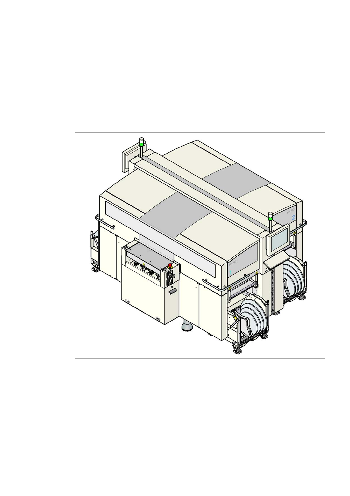
1 Introduction
These operating instructions provide a manual or reference work for operating and setting up the
SIPLACE
®
D3 placement machine.
The header of each chapter contains the release and software version, to which this manual ap-
plies.
1
Fig. 1.0 - 1 SIPLACE D3 placement machine