00195760-0102_UM_D3_SR605_EN.pdf - 第164页
3 Technical data for the machine User Manual SIPLACE D3 3.9 Feeder modules From software version SR.605.xx 07/2008 EN Edition 164 3.9.10.1 Description The dip m odule (item 1 in Fig. 3.9 - 18 ) is used to wet flip-chip a…
User Manual SIPLACE D3 3 Technical data for the machine
From software version SR.605.xx 07/2008 EN Edition 3.9 Feeder modules
163
3.9.9.4 Changing the retainer
→ Hold the retainer (G in Fig. 3.9 - 17, page 161) firmly. Press the thrust pad downwards (F in
Fig. 3.9 - 17
, page 161) and remove the retainer by pressing it out sideways.
3.9.9.5 Data entry
→ Define the waffle-pack trays as described in the SIPLACE Pro operating instructions.
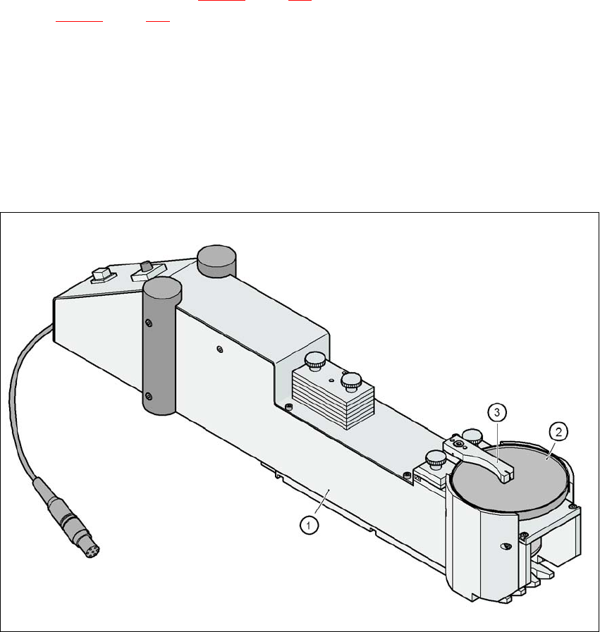
3.9.10 Dip module
Item no. 00117010-xx Dip module for flux and adhesives
3
Fig. 3.9 - 18 Dip module
(1) Dip module
(2) Rotating plate
(3) Squeegee

3 Technical data for the machine User Manual SIPLACE D3
3.9 Feeder modules From software version SR.605.xx 07/2008 EN Edition
164
3.9.10.1 Description
The dip module (item 1 in Fig. 3.9 - 18) is used to wet flip-chip and CSP components with flux or
conductive adhesive. The flux holder is a rotating plate (item 2 in Fig. 3.9 - 18
, page 163), on which
a thin film of flux (e.g. 40 μm) is created with a squeegee (item 3 in Fig. 3.9 - 18
, page 163). This
method is particularly suitable for highly viscous (honey-like) fluxes. The amount of flux required
for the process is reduced to a minimum coating thickness since only the undersides of the bumps
have to be wetted.
The Dip module is suitable for all the placement heads. It is regarded as a separate feeder module
type by the set-up optimization. There is no limit to the number of dip modules at the individual
locations.
3.9.10.2 Technical data
Locations filled 3
Component size Max. 36 x 36 mm²
depending on the placement head type
Possible coating thicknesses 25, 35, 45, 55, 65, 75 μm
Time required to change the coating thickness Less than 1 min.
Gap height tolerance ± 5 μm
Time for 1 revolution of the table Can be set using the potentiometer
from 0 - 10 s
Component dip time Programmable from 0 - 2 s
in 0.1 s increments
Flux Highly viscous flux, conductive adhesive
Further technical data and information on programming can be found in the Betriebsanleitung
DIP-Modul / DIP Module User Manual, item no. 00195065-xx.
3
User Manual SIPLACE D3 3 Technical data for the machine
From software version SR.605.xx 07/2008 EN Edition 3.10 Component trolley
165
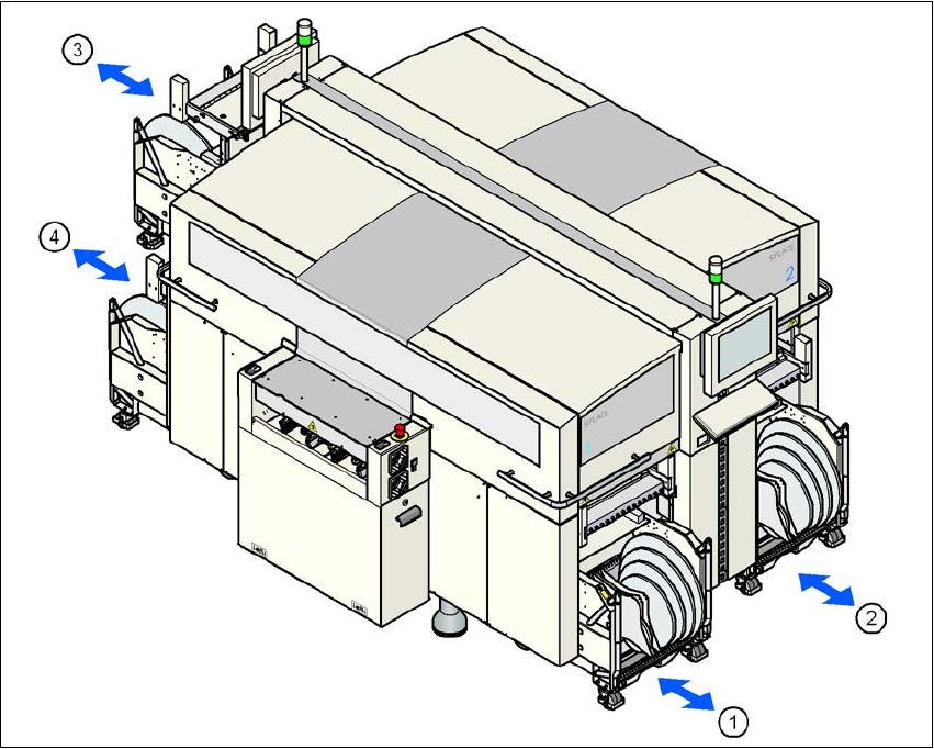
3.10 Component trolley
Item no. 00119622-xx Component trolley, SIPLACE HF/X/D3
Up to four component trolleys can be docked into the machine. The locations are numbered as
shown in the diagram below.
3
Fig. 3.10 - 1 Locations for the component trolleys
(1) Location 1
(2) Location 2
(3) Location 3
(4) Location 4
(T) PCB direction of travel
The component trolleys are stand-alone modules that can be set up with feeders at an external
set-up area. This means that the production process only has to be interrupted briefly in order to
change the component trolley.