00195760-0102_UM_D3_SR605_EN.pdf - 第165页
User Manual SIPLACE D3 3 Technical data for the machine From software version SR.605.xx 07/2008 EN Edition 3.10 Component trolley 165 3.10 Component trolley Item no. 001 19622-xx Component trolley , SIPLACE HF/X/D3 Up to…

3 Technical data for the machine User Manual SIPLACE D3
3.9 Feeder modules From software version SR.605.xx 07/2008 EN Edition
164
3.9.10.1 Description
The dip module (item 1 in Fig. 3.9 - 18) is used to wet flip-chip and CSP components with flux or
conductive adhesive. The flux holder is a rotating plate (item 2 in Fig. 3.9 - 18
, page 163), on which
a thin film of flux (e.g. 40 μm) is created with a squeegee (item 3 in Fig. 3.9 - 18
, page 163). This
method is particularly suitable for highly viscous (honey-like) fluxes. The amount of flux required
for the process is reduced to a minimum coating thickness since only the undersides of the bumps
have to be wetted.
The Dip module is suitable for all the placement heads. It is regarded as a separate feeder module
type by the set-up optimization. There is no limit to the number of dip modules at the individual
locations.
3.9.10.2 Technical data
Locations filled 3
Component size Max. 36 x 36 mm²
depending on the placement head type
Possible coating thicknesses 25, 35, 45, 55, 65, 75 μm
Time required to change the coating thickness Less than 1 min.
Gap height tolerance ± 5 μm
Time for 1 revolution of the table Can be set using the potentiometer
from 0 - 10 s
Component dip time Programmable from 0 - 2 s
in 0.1 s increments
Flux Highly viscous flux, conductive adhesive
Further technical data and information on programming can be found in the Betriebsanleitung
DIP-Modul / DIP Module User Manual, item no. 00195065-xx.
3
User Manual SIPLACE D3 3 Technical data for the machine
From software version SR.605.xx 07/2008 EN Edition 3.10 Component trolley
165
3.10 Component trolley
Item no. 00119622-xx Component trolley, SIPLACE HF/X/D3
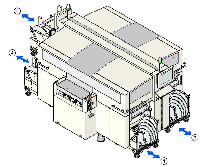
Up to four component trolleys can be docked into the machine. The locations are numbered as
shown in the diagram below.
3
Fig. 3.10 - 1 Locations for the component trolleys
(1) Location 1
(2) Location 2
(3) Location 3
(4) Location 4
(T) PCB direction of travel
The component trolleys are stand-alone modules that can be set up with feeders at an external
set-up area. This means that the production process only has to be interrupted briefly in order to
change the component trolley.
3 Technical data for the machine User Manual SIPLACE D3
3.10 Component trolley From software version SR.605.xx 07/2008 EN Edition
166
PLEASE NOTE:
At external set-up positions, you will need an external power supply for the component trolley
(see Section 3.10.6, page 171).
3
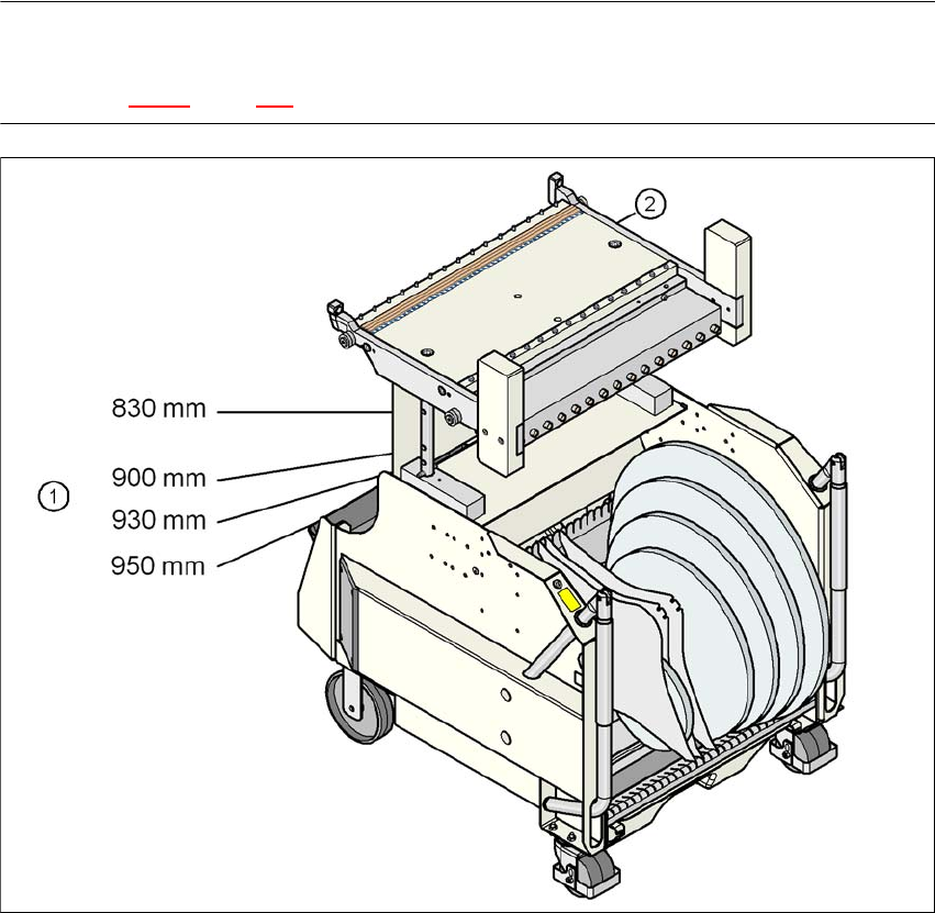
Fig. 3.10 - 2 Component trolley with a PCB conveyor height of 950 mm
3
(1) Holes in the guide columns for the conveyor heights of 830 to 950 mm
(2) Component trolley table
3.10.1 Structure
The component trolley essentially consists of the chassis, the component table for holding the
feeder modules, the communication unit, tape reel container and the waste container.