00195760-0102_UM_D3_SR605_EN.pdf - 第17页
User Manual SIPLACE D3 1 Introduction From software version SR.605.xx 07/2008 EN Edition 1.1 Description of the machine 17 1 The performance dat a can be found in Section 3.1 on page 97 . There are four locations fo r fe…
1 Introduction User Manual SIPLACE D3
1.1 Description of the machine From software version SR.605.xx 07/2008 EN Edition
16
1.1 Description of the machine
1.1.1 SIPLACE D3 placement machine
The SIPLACE D3 placement machine is characterized by its high configuration flexibility, excellent
placement rate and maximum precision. The machine covers the SMD spectrum of components
from 0201 to 125 x 10 mm² with a high placement rate.
Two placement methods are used:
– the Collect&Place method with Collect&Place heads for components from size 0201 to fine-
pitch
– the Pick&Place method with the SIPLACE TwinHead for fine-pitch and OSC components
The placement machine is based on a torsionally-rigid and vibration-damped cast steel machine
frame. This guarantees an excellent production quality and less environmental pollution for em-
ployees since the noise of shaking and vibration are reduced to a minimum.
The placement machine has three gantries. There is a placement head on each gantry. These can
be quickly and accurately positioned, moving independently of one another in the X and Y direc-
tions.
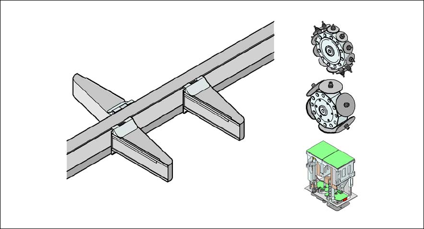
Depending on the placement job, a 6-segment or a 12-segment Collect&Place head or a Twin-
Head can be set up. This allows the following configurations:
1
1
Fig. 1.1 - 1 Head modularity - SIPLACE D3
Placement area 2
TH
C&P12
G1
G3
G4
C&P12/C&P6/TH
C&P12/C&P6/TH
C&P6
Placement area 1
C&P12/C&P6/TH

User Manual SIPLACE D3 1 Introduction
From software version SR.605.xx 07/2008 EN Edition 1.1 Description of the machine
17
1
The performance data can be found in Section 3.1 on page 97.
There are four locations for feeding components. Up to four component trolleys can be docked
into each machine. A matrix tray changer may be docked in at locations 2 and 4 in place of a com-
ponent trolley or a waffle-pack changer at location 2.
The placement heads fetch the components from the fixed feeder modules on the component trol-
leys or from the trays in the matrix tray changer, and place the PCBs, which are also stationary.
The placement machine has two placement areas.
– on the single conveyor, one or two PCBs can be placed concurrently.
– on the dual conveyor, up to four PCBs can be placed concurrently.
1.1.2 Selecting the placement head configuration
When you order a SIPLACE D-series placement system, you can select the ideal head configu-
ration for your needs. The placement machine will be configured and supplied as per your order.
There is also a reconfiguration kit if you wish to change the placement head locally. This package
contains the necessary assembly parts, cables, etc., in addition to the placement head. Before
changing the placement head, you should first adapt the station and SIPLACE Pro software. The
system will then have to be recalibrated.
Head modularity, i.e. adapting the machine to the production requirements by changing the place-
ment head, has the advantage that it is an easy way to match the machine to your production
needs without having to invest in further machines.
Placement area 1 Placement area 2
Gantry 1 Gantry 4 Gantry 3
Placement
head
C&P12 C&P12 C&P12
C&P12 C&P12 C&P6
C&P12 C&P12 TH
C&P12 C&P6 C&P6
C&P12 C&P6 TH
C&P12 TH TH
C&P6 C&P6 C&P6
C&P6 C&P6 TH
C&P6 TH TH
TH TH TH
1 Introduction User Manual SIPLACE D3
1.1 Description of the machine From software version SR.605.xx 07/2008 EN Edition
18
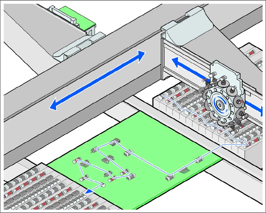
1.1.3 The SIPLACE principle
The principle of the "stationary component supply" and "stationary PCB", which has proved most
suitable for all SIPLACE machines, has a number of significant advantages:
– There are no downtimes for topping up components or splicing tapes.
– The vibration-free component feeder means that even the smallest components (e.g. 0201)
are picked up reliably.
– The PCB, which does not move during the placement process, prevents the components slip-
ping.
– The combination of placement heads with nozzle changers always guarantees an optimum
nozzle configuration for every placement process, thus minimizing traversing paths and opti-
mizing the placement sequence.
High flexibility, cost-effectiveness and set-up reliability combine to ensure that the SIPLACE D3
provides high productivity. Minimum down times increase utilization and thus help to increase pro-
ductivity.
1
Fig. 1.1 - 2 Placement principle using the Collect&Place method