00195760-0102_UM_D3_SR605_EN.pdf - 第179页
User Manual SIPLACE D3 4 Setting up and commissioning From software version SR.605.xx 07/2008 EN Edition 4.1 Transport and Delivery Configur ation 179 4 Fig. 4.1 - 2 Machine in the as-delivered configuration (1) Extensio…

4 Setting up and commissioning User Manual SIPLACE D3
4.1 Transport and Delivery Configuration From software version SR.605.xx 07/2008 EN Edition
178
4.1.2 Checking a delivery
→ Store the machine in the packaging until room temperature has been reached. There is oth-
erwise a risk of condensation occurring.
→ Check the delivery for damage.
→ Check the shock sensors.
→ Unpack the machine and the accessories and check the delivery for completeness (reference
delivery note).
→ Document the result in the installation report / acceptance testing report.
4.1.3 Configuration when delivered
The machine is configured as follows when delivered:
– The extension kit on the PCB output side (item 1 in Fig. 4.1 - 2
, page 179) is detached from
the basic machine.
– The axis unit (item 2 in Fig. 4.1 - 2
, page 179) in the extension kit on the PCB output side is
placed on a transport cushion. All cables are attached to the axis unit.
– The track on the single conveyor is set to a width of 210 mm. On the dual conveyor, the width
of conveyor track 1 is 100 mm and of conveyor track 2 is 210 mm. This width setting will be
important when fine-tuning the machine.
On the dual conveyor, the electrical plug-in connectors for the conveyor motor and light bar-
rier on the left-hand conveyor track are easily accessible and there is still enough space to fit
the output conveyor.
– The output conveyors (item 4 in Fig. 4.1 - 2
, page 179) of the single or dual conveyor are dis-
mantled. The electrical cables to the conveyor motors and light barriers are disconnected.
– Both keyboards (item 6 in Fig. 4.1 - 2
, page 179) are unplugged.
– The supporting plates for the keyboards (item 5 in Fig. 4.1 - 2
, page 179) are detached.
– Both monitors (item 7 in Fig. 4.1 - 2
, page 179) are dismantled.
– Both indicator lamps (item 8 in Fig. 4.1 - 2
, page 179) are dismantled.
– All the gantry axes are fixed with shipping braces.
User Manual SIPLACE D3 4 Setting up and commissioning
From software version SR.605.xx 07/2008 EN Edition 4.1 Transport and Delivery Configuration
179
4
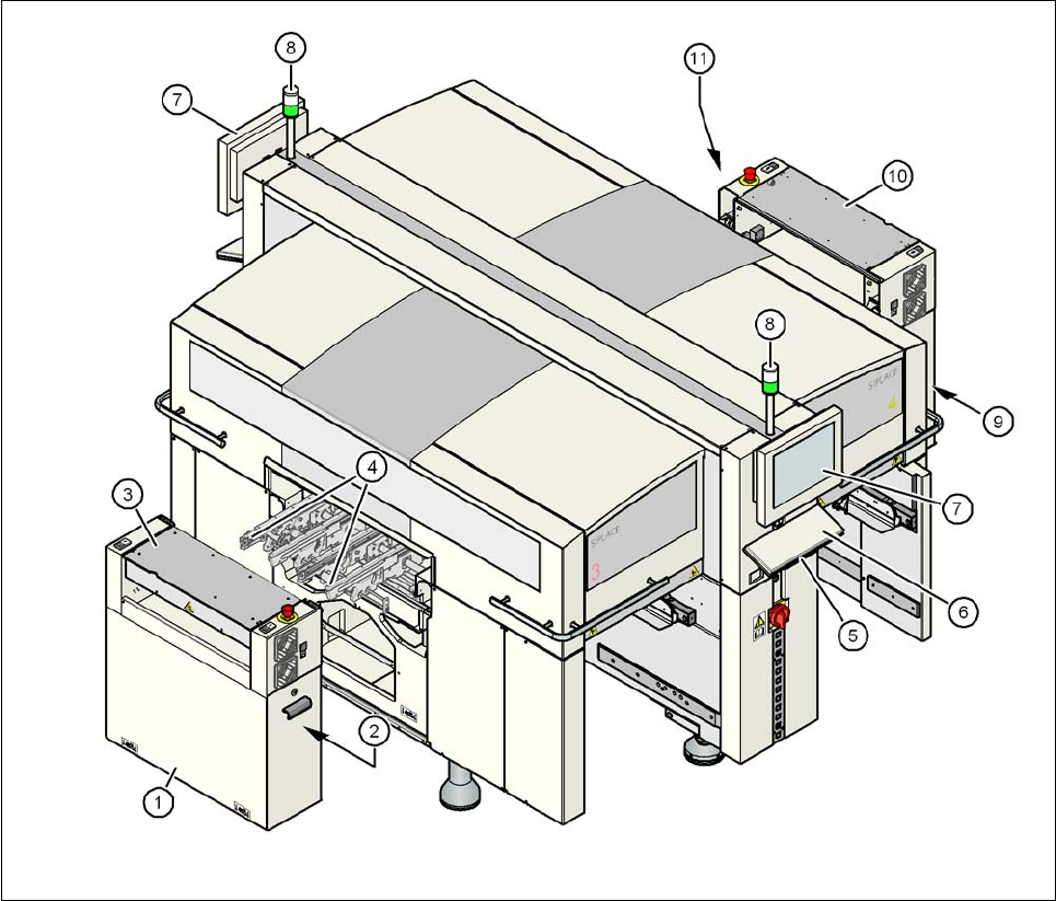
Fig. 4.1 - 2 Machine in the as-delivered configuration
(1) Extension kit on the PCB output side - detached for delivery
(2) Axis unit on the PCB output side - gantry 3
(3) PCB conveyor cover
(4) Output conveyor
(5) Keyboard supporting plate
(6) Keyboard
(7) Monitor
(8) Indicator lamp
(9) Computer unit / box PC unit on the PCB input side
(10) Extension kit on the PCB input side - may be removed if necessary
(11) Axis unit on the PCB input side - gantries 1 and 4

4 Setting up and commissioning User Manual SIPLACE D3
4.1 Transport and Delivery Configuration From software version SR.605.xx 07/2008 EN Edition
180
4.1.4 Transporting the machine in the crate
4.1.4.1 Services
SIPLACE can fully integrate the SIPLACE machines into your production line as a service to
you. With our extensive expertise and by using the right tools and equipment, we can ensure that
the installation process runs smoothly and efficiently. However, this will require you to clarify the
infrastructure aspects in advance and make any necessary changes at your production facility.
Please note that the safest way to transport the machine is always in the transport crate - or at the
very least on the pallet. This will prevent serious damage to the machine caused by the feet col-
liding with obstacles, for example.
4.1.4.2 Safety instructions
WARNING 4
– The applicable accident prevention regulations concerning the transportation of heavy goods
must be followed.
– There is a risk that the machine will tip over if you do not use the fork-lift specified in Section
4.1.4.3
, page 180 to transport the machine.
– In particular, you should wear safety boots to minimize the risk of crushing your feet.
4.1.4.3 Means of transport
A fork-lift truck with the following specification will be needed to carry the machine on the pallet or
in its crate:
Fork length: min. 1800 mm
Carrying power: min. 6000 kg
Clear width between forks: min. 350 mm 4
4