00195760-0102_UM_D3_SR605_EN.pdf - 第191页
User Manual SIPLACE D3 4 Setting up and commissioning From software version SR.605.xx 07/2008 EN Edition 4.2 Infrastructure at the installation location 191 4.2.3.4 Connecting the power supply c able 4 Fig. 4.2 - 4 T erm…
4 Setting up and commissioning User Manual SIPLACE D3
4.2 Infrastructure at the installation location From software version SR.605.xx 07/2008 EN Edition
190
WARNING 4
The electrical cables to each individual machine and to the installed options (e.g. MTC, produc-
tivity lift, vacuum pump) must be clearly identified and there must be no doubt as to their alloca-
tion. The regulations of the country in which the machine is operated apply.
4
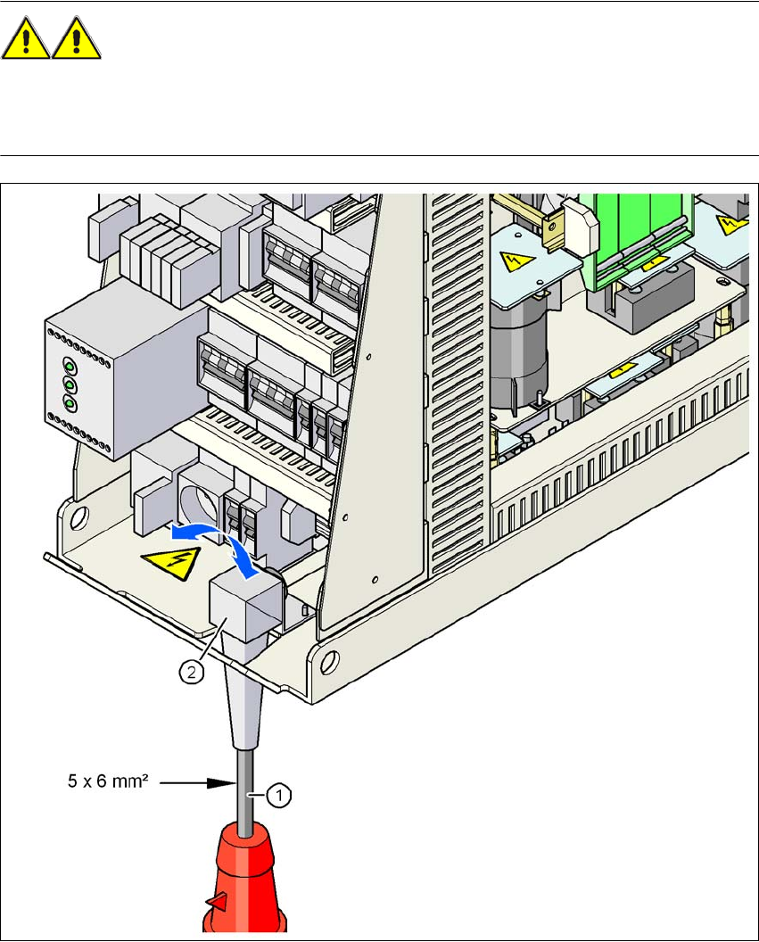
Fig. 4.2 - 3 Cross-section of the main power cable
(1) Power supply cable
(2) Angle for the cable gland
User Manual SIPLACE D3 4 Setting up and commissioning
From software version SR.605.xx 07/2008 EN Edition 4.2 Infrastructure at the installation location
191
4.2.3.4 Connecting the power supply cable
4
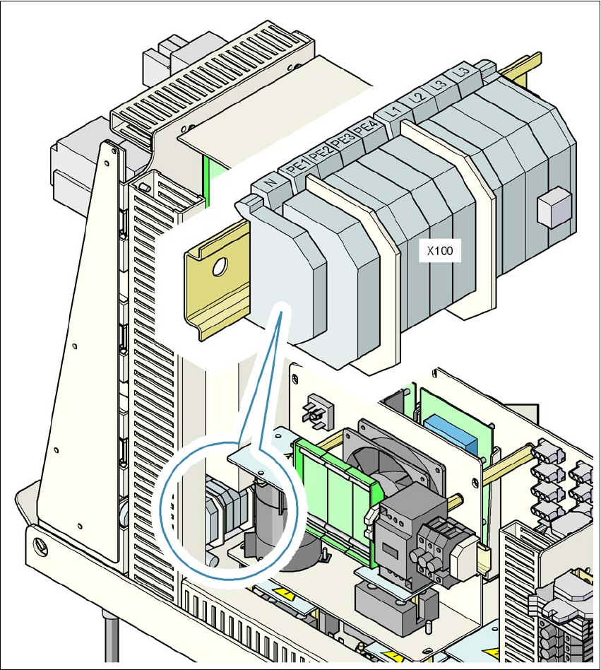
Fig. 4.2 - 4 Terminal panel for connecting the power cable
(L1) Three-phase
(L2) Three-phase
(L3) Three-phase
(N) Neutral conductor
(PE) Protective earth wires PE1, PE2, PE3, PE4
(X100) Terminal panel
4 Setting up and commissioning User Manual SIPLACE D3
4.2 Infrastructure at the installation location From software version SR.605.xx 07/2008 EN Edition
192
→ Crimp a ferrule onto each end of the wire.
→ Loosen the nuts on the angled cable gland (item 2 in Fig. 4.2 - 3
, page 190).
→ Fold up the angled cable gland.
→ Feed the power supply cable through the angled cable gland to the terminal panel X100 (see
X100 in Fig. 4.2 - 4
, page 191).
→ Connect the cable to the terminal and ensure that it has a sufficient bending radius. The wires
must not be kinked.
→ Fold up the angled cable gland (item 2 in Fig. 4.2 - 3
, page 190) and tighten the nuts hand-
tight.
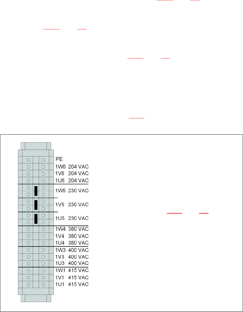
4.2.3.5 Checking connections to the primary side of the three-phase transformer T1
The primary side of the three-phase transformer T1 must be configured for the respective supply
voltage.
→ Therefore check at the terminal block (see Fig. 4.2 - 5
) to see whether the primary side of the
three-phase transformer T1 has been correctly connected for the respective supply voltage.
4
Fig. 4.2 - 5 Terminal block for the primary side of the three-phase transformer T1
See item 3 in Fig. 4.2 - 6, page 193 for the
position of the terminal block