00195760-0102_UM_D3_SR605_EN.pdf - 第194页
4 Setting up and commissioning User Manual SIPLACE D3 4.2 Infrastructure at the installation location From software version SR.605.xx 07/2008 EN Edition 194 4.2.3.6 Checking the inrush current limit ation jumpers The inr…
User Manual SIPLACE D3 4 Setting up and commissioning
From software version SR.605.xx 07/2008 EN Edition 4.2 Infrastructure at the installation location
193
PLEASE NOTE 4
The Japanese supply network (3 x 200 VAC) and supply networks in the USA (3 x 208 VAC) are
connected to terminals for 3 x 204 VAC.
4
4
4
4
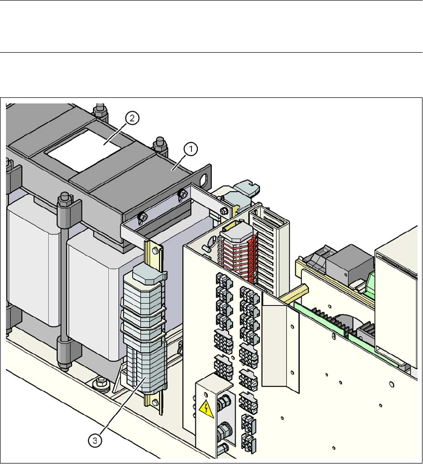
Fig. 4.2 - 6 Position of the terminal block with primary connections for the three-phase transformer T1
(1) Three-phase transformer T1
(2) Sign with the connection wiring diagram for the primary side
(3) Terminal block with primary connections for the three-phase transformer T1
4 Setting up and commissioning User Manual SIPLACE D3
4.2 Infrastructure at the installation location From software version SR.605.xx 07/2008 EN Edition
194
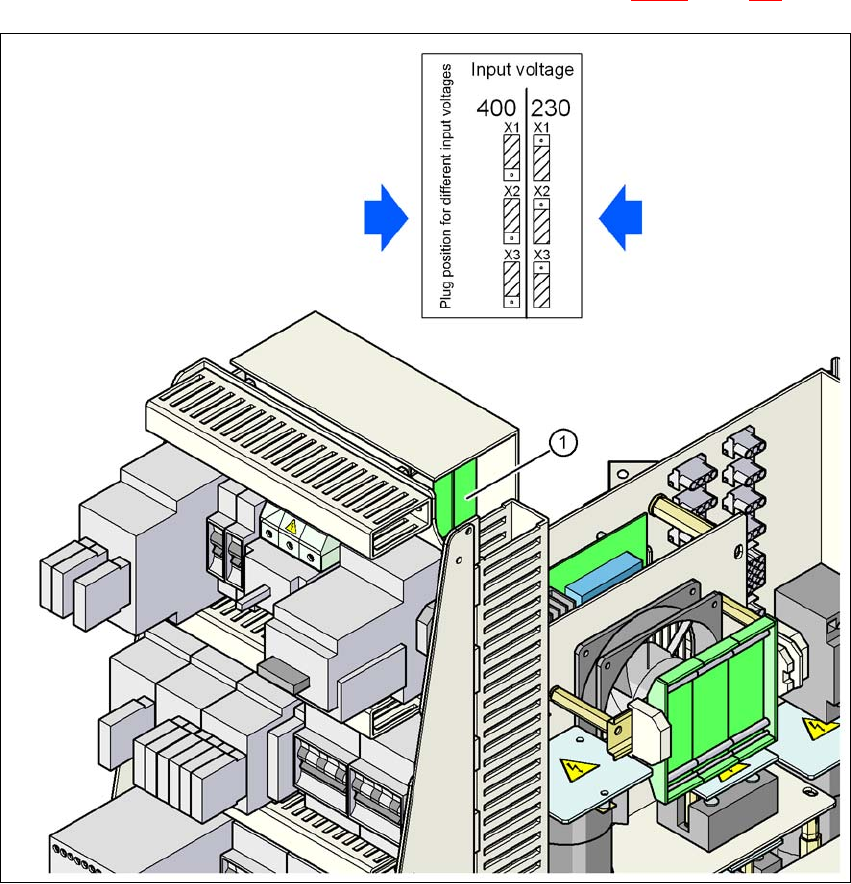
4.2.3.6 Checking the inrush current limitation jumpers
The inrush current limitation must be configured in relation to the supply voltage. This is done us-
ing plug-in jumpers on the inrush current limitation board (item 1 in Fig. 4.2 - 7
, page 194).
4
Fig. 4.2 - 7 Position of the board and connectors for the inrush current limitation
4
(1) Inrush current limitation board
X1, X2, X3 Connectors for configuring the inrush current limitation on the board
→ Check the jumper assignment and correct if necessary.
3 x 380 VAC
3 x 400 VAC
3 x 415 VAC
3 x 200 VAC
3 x 208 VAC
3 x 230 VAC
User Manual SIPLACE D3 4 Setting up and commissioning
From software version SR.605.xx 07/2008 EN Edition 4.3 Setting up the machine
195
4.3 Setting up the machine
4.3.1 PCB conveyor heights on the machine
The machine can be set to the following PCB conveyor heights:
830 mm ± 15 mm (standard height) 4
900 mm ± 15 mm 4
930 mm ± 15 mm 4
950 mm ± 15 mm (SMEMA height) 4
PLEASE NOTE 4
The PCB conveyor height is the distance between the top edge of the PCB conveyor belt and the
bottom edge of the machine feet.
4.3.2 Warning instructions
DANGER 4
Only SIPLACE engineers or qualified people are permitted to set up and commission the machine.
→ Always follow the applicable accident prevention regulations.
→ Never lie beneath the machine in order to attach the machine feet. All the modules and parts
can be fitted from the spaces for the component tables. If you nevertheless have to carry out
assembly work underneath the machine, then you must secure the machine by suitable
means. The fork-lift must not be used as the only support.
→ Make sure that the gantries are positioned over the PCB conveyor area so that you do not
restrict your head movement during assembly, thus excluding the risk of injury.
→ Two people will be needed to adjust the height of the machine:
– one person to carry out the necessary assembly work,
– the other person to watch the raised machine during assembly and ensure that it does
not move.
→ Wear special safety boots to protect your feet. Each machine foot weighs 6.75 kg.