00195760-0102_UM_D3_SR605_EN.pdf - 第201页
User Manual SIPLACE D3 4 Setting up and commissioning From software version SR.605.xx 07/2008 EN Edition 4.3 Setting up the machine 201 – The opening in the space r on the power supply side poin ts against the dir ection…
4 Setting up and commissioning User Manual SIPLACE D3
4.3 Setting up the machine From software version SR.605.xx 07/2008 EN Edition
200
4.3.4.1 Presetting the height of the middle machine feet
The middle machine feet are preset first. The spacer must be bolted to the underside in the correct
position for the machine height.
Setting the PCB conveyor height to 830 mm 4
You will not need a spacer for a PCB conveyor height of 830 mm.
→ Screw the middle machine foot as far as possible into the thread provided (see point 5 in Fig.
4.3 - 3
, page 199).
Setting the PCB conveyor height to 900 mm 4
You will need the spacer for a PCB conveyor height of 900 mm.
→ Align the spacer so that the 90 mm side is vertical and the hole for the middle machine foot
points downwards.
4
4
4
4
4
4
4
4
4
4
4
4
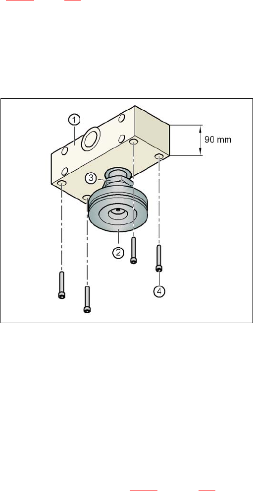
Fig. 4.3 - 4 Alignment of the spacer for a conveyor height of 900 mm
4
(1) Spacer height 90 mm
(2) Middle machine foot
(3) M24 lock nut
(4) Hexagon socket head screw M12x80, 4x
→ Screw the thread of the middle machine foot into the hole on the underside of the spacer.
→ Align the two spacers on the underside of the machine as follows:
– The opening in the spacer on the pneumatic unit side points in the direction of PCB trans-
port (see point 4 in Fig. 4.3 - 3
on page 199).
User Manual SIPLACE D3 4 Setting up and commissioning
From software version SR.605.xx 07/2008 EN Edition 4.3 Setting up the machine
201
– The opening in the spacer on the power supply side points against the direction of PCB
transport (see point 3 in Fig. 4.3 - 3
on page 199).
→ Fix each spacer using four hexagon socket head screws M12x80 (see point 4 in Fig. 4.3 - 4
,
page 200
). using the size 10 mm screwdriver bit.
Setting the PCB conveyor height to 930 mm and 950 mm 4
You will also need the spacer for PCB conveyor heights of 930 mm and 950 mm.
→ Align the spacer so that the 122.5 mm side is vertical and the hole for the middle machine foot
points downwards.
4
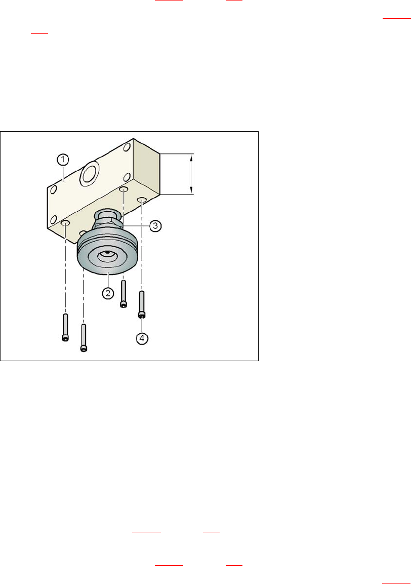
Fig. 4.3 - 5 Alignment of the spacer for conveyor heights of 930 and 950 mm
4
(1) Spacer height 122.5 mm
(2) Machine foot
(3) M24 lock nut
(4) Hexagon socket head screw M12x80, 4x
→ Screw the thread of the middle machine foot into the hole on the underside of the spacer.
→ Align the two spacers as follows:
– The opening in the spacer on the pneumatic unit side points in the direction of PCB trans-
port (see point 4 in Fig. 4.3 - 3
on page 199).
– The opening in the spacer on the power supply side points against the direction of PCB
transport (see point 3 in Fig. 4.3 - 3
on page 199).
→ Fix each spacer using four hexagon socket head screws M12x80 (see point 4 in Fig. 4.3 - 5
)
using the size 10 mm screwdriver bit.
122.5 mm
4 Setting up and commissioning User Manual SIPLACE D3
4.3 Setting up the machine From software version SR.605.xx 07/2008 EN Edition
202
4.3.4.2 Presetting the height of the outer machine feet
4
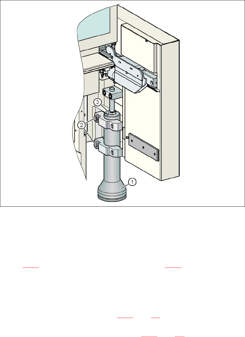
Fig. 4.3 - 6 Presetting the height of the outer machine feet
(1) Machine foot - 2 versions
(2) M24x90 hexagon socket head screw
(3) M24x2x120 adjusting screw
→ Use the 19 mm bit to loosen the two hexagon socket head screws M24x90 (item 2 in
Fig. 4.3 - 6
), and allow the outer machine foot (item 1 in Fig. 4.3 - 6) to slide down slowly as
far as the stop.
→ Insert the correct machine foot for the required PCB conveyor height.
There are two versions of the outer machine feet: 4
– outer machine foot for the PCB conveyor height of 830 mm, length 369 mm,
item no. 03041008-01 (item 1 in Fig. 4.3 - 3
, page 199)
– outer machine foot for the PCB conveyor heights of 900, 930 and 950 mm, length
439 mm, item no. 03000890-02 (item 2 in Fig. 4.3 - 3
, page 199)