00195760-0102_UM_D3_SR605_EN.pdf - 第204页
4 Setting up and commissioning User Manual SIPLACE D3 4.3 Setting up the machine From software version SR.605.xx 07/2008 EN Edition 204 4.3.5 Fitting the extension ki t s to the machine frame 4.3.5.1 Fitting the extensio…

User Manual SIPLACE D3 4 Setting up and commissioning
From software version SR.605.xx 07/2008 EN Edition 4.3 Setting up the machine
203
→ Preset the height for each of the outer machine feet.
The distance between the underside of the machine foot and the bottom edge of the machine
frame should be as follows:
→ Use the size 36 fork wrench to turn the adjusting screw M24x2x120 (item 3 in Fig. 4.3 - 6
,
page 202
) until you obtain the distance values given in the above table for the particular con-
veyor height.
→ Now use the fork-lift to carefully lower the machine until the machine feet touch the floor
evenly. There should always be a second person present to ensure that the machine remains
stable while it is being lowered. It may be necessary to loosen the outer machine feet clamps
slightly.
→ Continue carefully lowering the machine until the outer machine feet touch the screws
M24x2x120 (item 3 in Fig. 4.3 - 6
, page 202) for adjusting the height.
→ Make sure that the middle machine feet (see point 2 in Fig. 4.3 - 3
, page 199) do not yet touch
the floor. If necessary, screw the middle machine feet into the machine or spacer slightly.
PLEASE NOTE 4
A description of how to definitively adjust the machine can be found in Section 4.3.18
on
page 243.
PCB conveyor height Distance from underside of machine foot
to bottom edge of machine frame
830 mm 120 mm
900 mm 190 mm
930 mm 220 mm
950 mm 240 mm

4 Setting up and commissioning User Manual SIPLACE D3
4.3 Setting up the machine From software version SR.605.xx 07/2008 EN Edition
204
4.3.5 Fitting the extension kits to the machine frame
4.3.5.1 Fitting the extension kit on the PCB output side
When the machine is delivered, the extension kit on the PCB output side and the PCB output con-
veyor are dismantled. The procedure for attaching the extension kit to the PCB output side is as
follows:
– Fitting the output conveyor
see Section 4.3.6, page 205
– Fitting the extension kit on the PCB output side see Section 4.3.7, page 206
– Installing the axis unit see Section 4.3.8, page 212
– Fitting the indicator lamps see Section 4.3.14, page 232
– Integrating the machine into the line see Section 4.3.17, page 240
– Making final adjustments to the machine see Section 4.3.18, page 243
4.3.5.2 Fitting the extension kit on the PCB input side
If the extension kit on the PCB input side was also removed for ease of transportation, you will
have to carry out the following steps before integrating the machine into the line (see Section
4.3.17
, page 240):
– Fitting the input conveyor
see Section 4.3.9, page 215
– Fitting the extension kit on the PCB input side see Section 4.3.10, page 217
– Fitting the box PC unit see Section 4.3.11, page 221
– Installing the computer unit see Section 4.3.12, page 226
– Installing the axis unit see Section 4.3.13, page 230
– Fitting the indicator lamps see Section 4.3.14, page 232
– Integrating the machine into the line see Section 4.3.17, page 240
– Making final adjustments to the machine see Section 4.3.18, page 243
User Manual SIPLACE D3 4 Setting up and commissioning
From software version SR.605.xx 07/2008 EN Edition 4.3 Setting up the machine
205
4.3.6 Fitting the output conveyor
4.3.6.1 Tools
– Allen keys, DIN 911, set
– Phillips screwdriver, size 1
4.3.6.2 Assembly
4
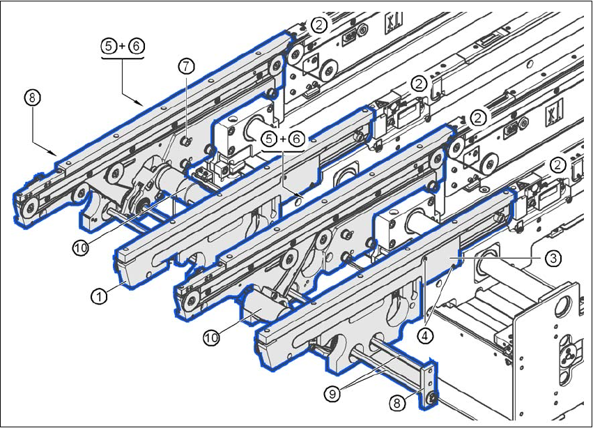
Fig. 4.3 - 7 Output conveyor - dual conveyor
(1) Rail, output conveyor
(2) Rail, processing conveyor 2
(3) Cable cover 20 x 200
(4) Countersunk screw, ISO 7046, M3x6, 2x per cable cover
(5) Cable cover 20 x 310
(6) Fillister head screw DIN 912, M3x5, 1x per cable cover
(7) Fillister head screw DIN 912, M6x16, and washer, 4x per rail
(8) Guide for hexagonal shaft
(9) Hexagonal shaft (single conveyor: one, dual conveyor: two)
(10) Drive unit