00195760-0102_UM_D3_SR605_EN.pdf - 第213页
User Manual SIPLACE D3 4 Setting up and commissioning From software version SR.605.xx 07/2008 EN Edition 4.3 Setting up the machine 213 4.3.8.2 Axis unit (gantry 3) - Connecting the pl ugs → Connect the po wer cable as s…
4 Setting up and commissioning User Manual SIPLACE D3
4.3 Setting up the machine From software version SR.605.xx 07/2008 EN Edition
212
4.3.8 Installing the axis unit
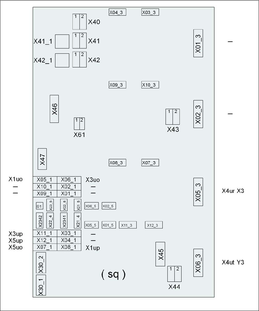
4.3.8.1 Axis unit (gantry 3) - Electrical connection points
4
Fig. 4.3 - 11 Axis unit (gantry 3), back panel - Electrical connection points
Plug
Plug
Plug

User Manual SIPLACE D3 4 Setting up and commissioning
From software version SR.605.xx 07/2008 EN Edition 4.3 Setting up the machine
213
4.3.8.2 Axis unit (gantry 3) - Connecting the plugs
→ Connect the power cable as shown in the following diagram:
4
4
→ Check the switch settings for S1
1: ON
2: Not used
Axis unit, plugs Connecting cable PLEASE NOTE
Plug Cable
X41_1sq X41_1sq 03050899 Snap connector into place
X42_1sq X42_1sq 03050899 Snap connector into place
X45sq X45sq 03050900-W1 Snap connector into place
X46sq X46sq
03050900-W2
03050900-W3
Snap connector into place
X47sq X47sq
03050900-W4
03050900-W5
Snap connector into place
X05_3sq X4ur 03050901 Snap connector into place
X06_3sq X4ut 03050902 Snap connector into place
X05_1sq X1uo 03009811 Insert as far as the stop
X06_1sq X3uo 03009812 Insert as far as the stop
X07_1sq X5uo 03009813 Insert as far as the stop
X08_1sq X1up 03009814 Insert as far as the stop
X11_1sq X3up 03009815 Insert as far as the stop
X12_1sq X5up 03009816 Insert as far as the stop
X07_3sq X07_3sq 03050903 Snap connector into place
X08_3sq X08_3sq 03050904 Snap connector into place
X11_3sq X11_3sq 03050906 Snap connector into place
X12_3sq X12_3sq 03050905 Snap connector into place
X30_1sq X30_1sq 03010054 Screw tightly
X30_2sq X30_2sq 03010054 Screw tightly

4 Setting up and commissioning User Manual SIPLACE D3
4.3 Setting up the machine From software version SR.605.xx 07/2008 EN Edition
214
4.3.8.3 Fitting the axis unit
→ Carefully lift the axis unit onto the rail in the extension kit.
→ Make sure that you do not squash any cables.
→ Push the axis unit into the extension kit as far as the stop.
→ Secure the axis unit with the fillister head screw.
→ Insert the cover.
→ Fix the grounding cable to the doors (item 2 in Fig. 4.3 - 8
, page 207),
as shown in Fig. 4.3 - 9
on page 210.
→ Lock the doors.
4.3.8.4 Fitting the side plates
→ Fix the grounding cable to each side plate (item 6 in Fig. 4.3 - 8, page 207), as shown in Fig.
4.3 - 9
page 210.
→ Fix the side plate to the machine frame with 6 fillister head screws.
PLEASE NOTE 4
If you have dismantled the output conveyor, continue from Section 4.3.9
" Fitting the input con-
veyor" on page 215.
Once the input conveyor is fitted, then continue the assembly work from Section 4.3.14
"Fitting
the indicator lamps" on page 232.