00195760-0102_UM_D3_SR605_EN.pdf - 第218页
4 Setting up and commissioning User Manual SIPLACE D3 4.3 Setting up the machine From software version SR.605.xx 07/2008 EN Edition 218 → Release the two hor izontal ten sioners (item 6 in Fig. 4.3 - 13 , page 217 ). CAU…
User Manual SIPLACE D3 4 Setting up and commissioning
From software version SR.605.xx 07/2008 EN Edition 4.3 Setting up the machine
217
4.3.10 Fitting the extension kit on the PCB input side
4.3.10.1 Tools
– Allen keys, DIN 911, set
– Machine key
4.3.10.2 Assembly
4
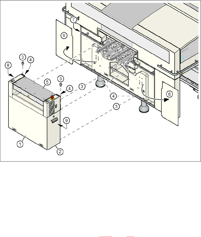
Fig. 4.3 - 13 Fitting the extension kit on the PCB input side
(1) Extension kit, dismantled
(2) Door
(3) Fillister head screw DIN 912, M6x16 and washer
(4) Ground connection point
(5) Conveyor cover
(6) Side panel, detached
(7) Drawer unit rail
(8) Computer unit or box PC unit (see Section 4.3.11
, page 221)
(9) Axis unit
4 Setting up and commissioning User Manual SIPLACE D3
4.3 Setting up the machine From software version SR.605.xx 07/2008 EN Edition
218
→ Release the two horizontal tensioners (item 6 in Fig. 4.3 - 13, page 217).
CAUTION 4
Do not unscrew the three bottom screws straight away. Simply loosen them so that the side
plate does not fall off.
→ Detach the ground cable from the side plate.
→ Remove both doors (item 2 in Fig. 4.3 - 13
, page 217) from the extension kit (item 1).
PLEASE NOTE: 4
To avoid damage, we recommend that a second person helps to assemble the extension kit.
→ Set down the computer unit / box PC unit
a
(item 8 in Fig. 4.3 - 13, page 217) and the axis unit
(item 9 in Fig. 4.3 - 13
, page 217) at the side of the machine in order to make enough space
to fit the extension kit (item 1 in Fig. 4.3 - 13
, page 217).
→ Make sure that the connecting cables to the computer unit / box PC unit
a
and the axis unit
are not too tight.
→ Lift the extension kit (item 1 in Fig. 4.3 - 13
, page 217) against the machine frame and position
it so that the assembly bracket lies on the drawer unit rail (item 7 in Fig. 4.3 - 13
, page 217).
CAUTION 4
Make sure that the extension kit does not collide with the hexagonal shaft of the PCB con-
veyor and thus become bent.
→ Fix the extension kit using 4 fillister head screws M6x16 and the associated washers (item 3
in Fig. 4.3 - 13
, page 217).
4.3.10.3 Fitting the guide for the hexagonal shaft
→ On the single conveyor, fix one guide for the hexagonal shaft (item 8 in Fig. 4.3 - 12) to the
extension kit using two fillister head screws M6x16 and washers.
→ On the double conveyor, fix two guides for the hexagonal shaft (item 8 in Fig. 4.3 - 12
) to the
extension kit using two fillister head screws M6x16 and washers.
a) See Section 4.3.11, page 221

User Manual SIPLACE D3 4 Setting up and commissioning
From software version SR.605.xx 07/2008 EN Edition 4.3 Setting up the machine
219
4.3.10.4 Producing cable connections - extension kit on the PCB input side
4
Left-hand side of the extension kit
(viewed in the direction of travel)
Connector/cable To connector/
cable
Start/stop button
Switch, PCB conveyor cover
X61/03020410 X61/03002537
Protective cover switch, location 4
X54/03020409 X54/03002540
Button for the component trolley docking unit, loca-
tion 4
X242/03021056 X242/03021054
Right-hand side of the extension kit
(viewed in the direction of travel)
Connector/cable To connector/
cable
EMERGENCY STOP button
Start/stop button
X64/03020687 X64/03002538
Protective cover switch, location 1
X51/03020409 X51/03002539
Button for the component trolley docking unit, loca-
tion 1
X212/03021056 X212/03021051