00195760-0102_UM_D3_SR605_EN.pdf - 第220页
4 Setting up and commissioning User Manual SIPLACE D3 4.3 Setting up the machine From software version SR.605.xx 07/2008 EN Edition 220 4.3.10.5 Fitting the grounding cable for the doors → Fix the two grounding cables fo…

User Manual SIPLACE D3 4 Setting up and commissioning
From software version SR.605.xx 07/2008 EN Edition 4.3 Setting up the machine
219
4.3.10.4 Producing cable connections - extension kit on the PCB input side
4
Left-hand side of the extension kit
(viewed in the direction of travel)
Connector/cable To connector/
cable
Start/stop button
Switch, PCB conveyor cover
X61/03020410 X61/03002537
Protective cover switch, location 4
X54/03020409 X54/03002540
Button for the component trolley docking unit, loca-
tion 4
X242/03021056 X242/03021054
Right-hand side of the extension kit
(viewed in the direction of travel)
Connector/cable To connector/
cable
EMERGENCY STOP button
Start/stop button
X64/03020687 X64/03002538
Protective cover switch, location 1
X51/03020409 X51/03002539
Button for the component trolley docking unit, loca-
tion 1
X212/03021056 X212/03021051
4 Setting up and commissioning User Manual SIPLACE D3
4.3 Setting up the machine From software version SR.605.xx 07/2008 EN Edition
220
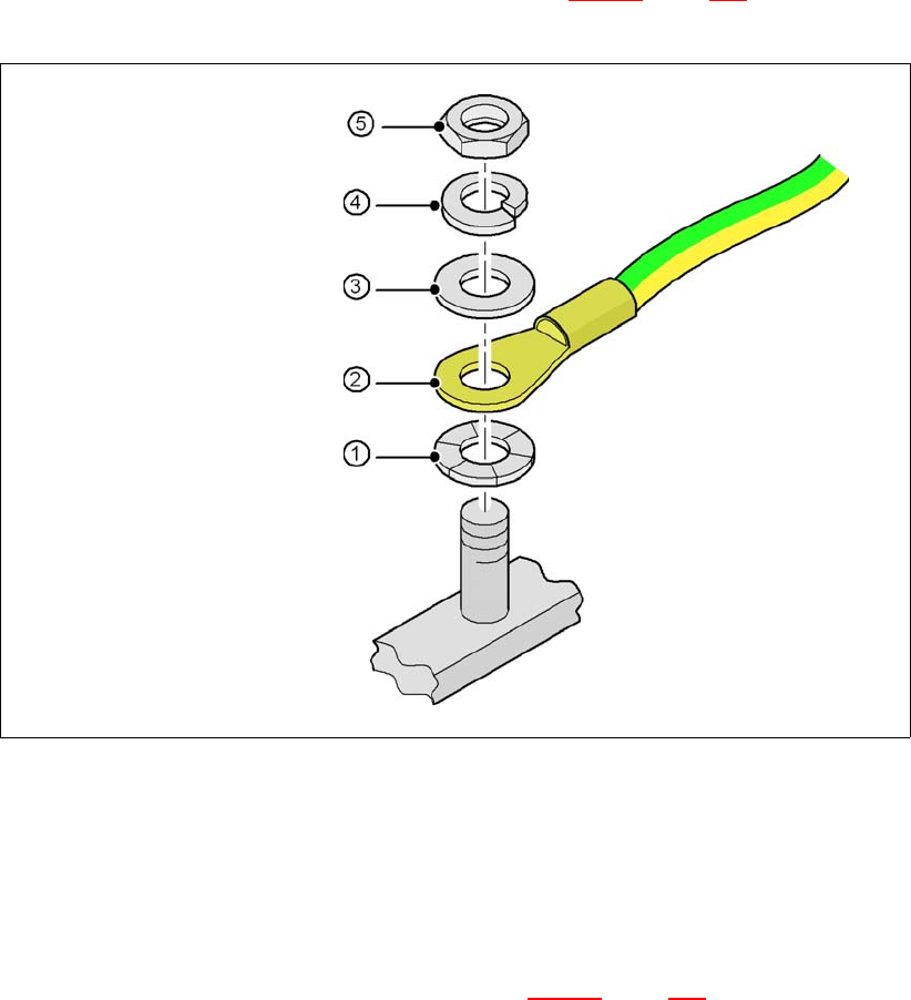
4.3.10.5 Fitting the grounding cable for the doors
→ Fix the two grounding cables for the doors (item 4 in Fig. 4.3 - 13, page 217) to the machine
frame as follows:
4
Fig. 4.3 - 14 Fitting the grounding cable
4
4
4
4
4
4.3.10.6 Checking and setting the protective cover switch
→ Check that the protective cover switch (item 7 in Fig. 4.3 - 15, page 221) is working correctly.
→ Adjust the protective cover switch if necessary (see service manual).
4
Hex nut M5
Spring washer M5, DIN 7980
Washer M5, DIN 125
Cable lug, annular
Contact washer
User Manual SIPLACE D3 4 Setting up and commissioning
From software version SR.605.xx 07/2008 EN Edition 4.3 Setting up the machine
221
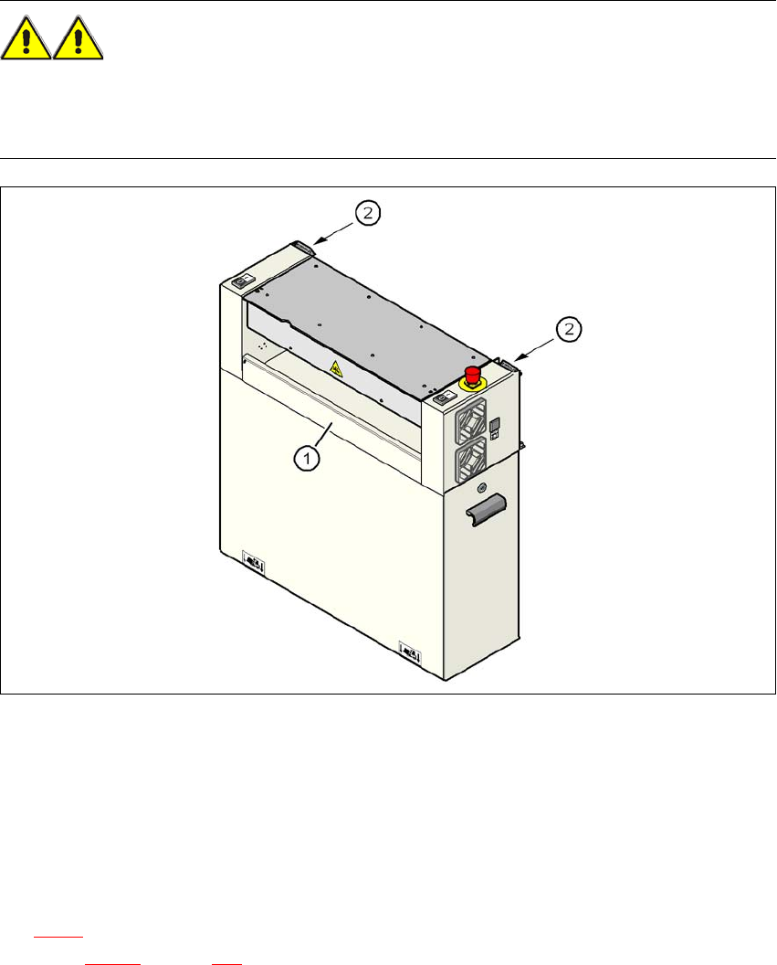
4.3.10.7 Installing the "bottom" hand guard
The machines are supplied with just one "bottom" hand guard. If the machines are installed within
a line, then no hand guard is required between immediately adjacent output and input conveyors.
WARNING 4
Always fit the "bottom" hand guard (item no. 03003432-01) on the input side of the first machine
and on the output side of the last machine of a line using 4 hexagon socket head screws M4x12.
This will prevent your personnel reaching into the machine without authorization.
4
Fig. 4.3 - 15 Fitting the "bottom" hand guard on the PCB input side
(1) "Bottom" hand guard, item no. 03003432-01
(2) Protective cover switch
4
4.3.11 Fitting the box PC unit
The placement machine can be equipped with the box PC unit or the computer unit. Refer to Sec-
tion 4.3.11
for installing the box PC. A description of how to install the computer unit can be found
in Section 4.3.12
on page 226.