00195760-0102_UM_D3_SR605_EN.pdf - 第222页
4 Setting up and commissioning User Manual SIPLACE D3 4.3 Setting up the machine From software version SR.605.xx 07/2008 EN Edition 222 4.3.1 1.1 Box PC unit - electrical connection point s 4 Fig. 4.3 - 16 Box PC unit, f…
User Manual SIPLACE D3 4 Setting up and commissioning
From software version SR.605.xx 07/2008 EN Edition 4.3 Setting up the machine
221
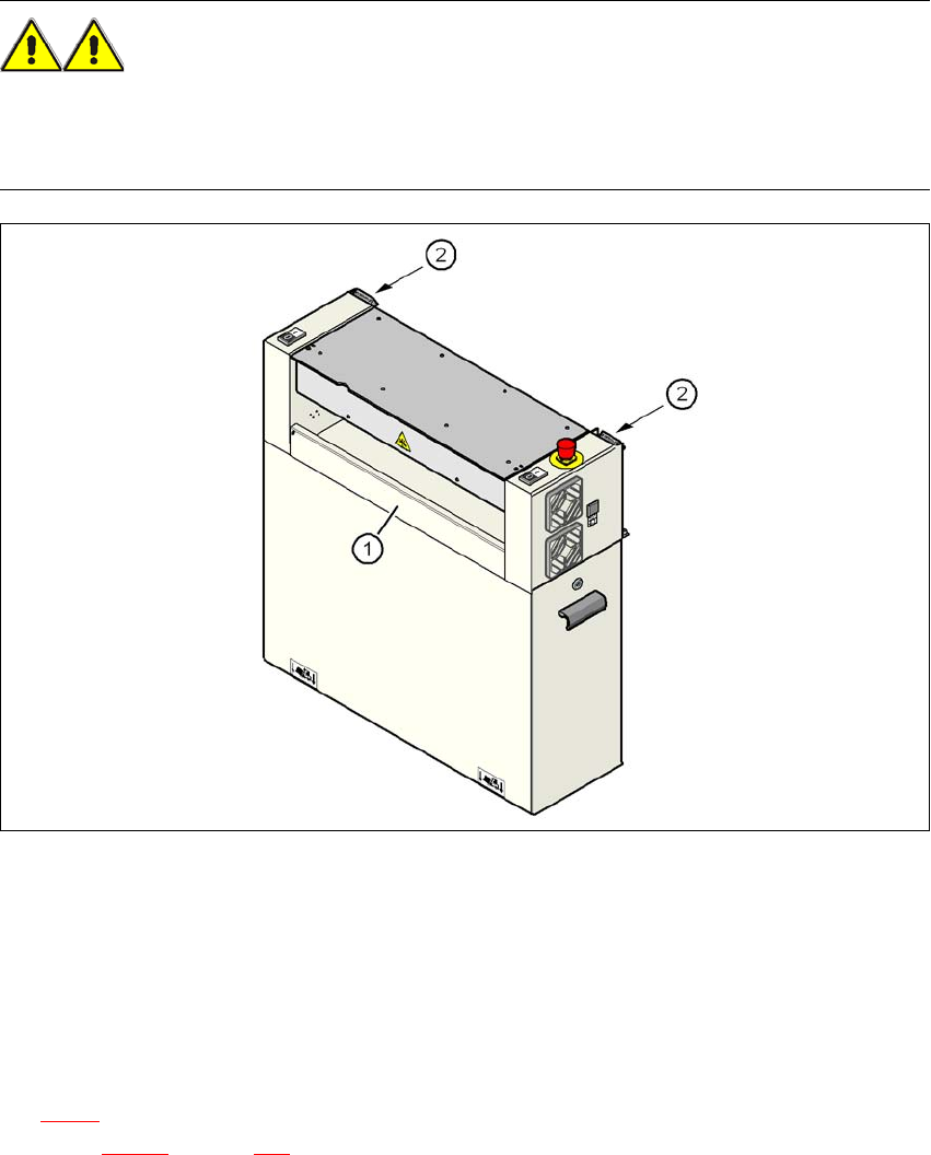
4.3.10.7 Installing the "bottom" hand guard
The machines are supplied with just one "bottom" hand guard. If the machines are installed within
a line, then no hand guard is required between immediately adjacent output and input conveyors.
WARNING 4
Always fit the "bottom" hand guard (item no. 03003432-01) on the input side of the first machine
and on the output side of the last machine of a line using 4 hexagon socket head screws M4x12.
This will prevent your personnel reaching into the machine without authorization.
4
Fig. 4.3 - 15 Fitting the "bottom" hand guard on the PCB input side
(1) "Bottom" hand guard, item no. 03003432-01
(2) Protective cover switch
4
4.3.11 Fitting the box PC unit
The placement machine can be equipped with the box PC unit or the computer unit. Refer to Sec-
tion 4.3.11
for installing the box PC. A description of how to install the computer unit can be found
in Section 4.3.12
on page 226.
4 Setting up and commissioning User Manual SIPLACE D3
4.3 Setting up the machine From software version SR.605.xx 07/2008 EN Edition
222
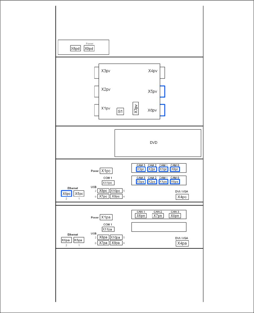
4.3.11.1 Box PC unit - electrical connection points
4
Fig. 4.3 - 16 Box PC unit, front panel - connecting the plugs
USB hub
Video multiplexer
Control computer
Machine controller
User Manual SIPLACE D3 4 Setting up and commissioning
From software version SR.605.xx 07/2008 EN Edition 4.3 Setting up the machine
223
4
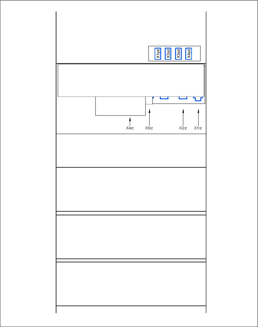
Fig. 4.3 - 17 Box PC unit, rear panel - connecting the plugs
USB hub
DC/DC converter
Control computer
Machine controller
Box PC voltage distributor