00195760-0102_UM_D3_SR605_EN.pdf - 第226页
4 Setting up and commissioning User Manual SIPLACE D3 4.3 Setting up the machine From software version SR.605.xx 07/2008 EN Edition 226 4.3.12 Inst alling the computer unit 4.3.12.1 Computer unit - Electrical connection …

User Manual SIPLACE D3 4 Setting up and commissioning
From software version SR.605.xx 07/2008 EN Edition 4.3 Setting up the machine
225
4.3.11.3 Box PC unit - plug-in connectors on the rear panel
4
4
4.3.11.4 Fitting the box PC unit
→ Plug in the plug-in connectors on the back panel of the box PC unit (see Section 4.3.11.3).
→ Carefully lift the box PC unit onto the rail in the extension kit.
→ Make sure that you do not squash any cables.
→ Push the box PC unit into the extension kit as far as the stop.
→ Plug in the plug-in connectors on the front panel of the box PC unit (see Section 4.3.11.2
,
page 224
).
→ Fix the cables to the front panel with cable ties.
→ Secure the box PC unit with the fillister head screw.
→ Fix the grounding cable to the doors (item 2 in Fig. 4.3 - 13
, page 217),
as shown in Fig. 4.3 - 14
on page 220.
→ Lock the doors.
PLEASE NOTE 4
If the box PC unit is installed, continue from Section 4.3.13 on page 230.
Box PC unit, rear panel
(Fig. 4.3 - 17
, page 223)
Plug
Connecting cable PLEASE NOTE
Plug Cable
PE1 Cable ring Grounding cable
Fix as shown in Fig. 4.3 - 14
,
page 220
.
X1rz X1rz 03051757 Insert as far as the stop
X3rz X3rz 03050907 Insert as far as the stop
X1pd X1pd 03051751 Insert as far as the stop
X2pd X2pd 03051752 Insert as far as the stop
X3pd X3pd 03051753 Insert as far as the stop
X4pd X4pd 03051754 Insert as far as the stop
4 Setting up and commissioning User Manual SIPLACE D3
4.3 Setting up the machine From software version SR.605.xx 07/2008 EN Edition
226
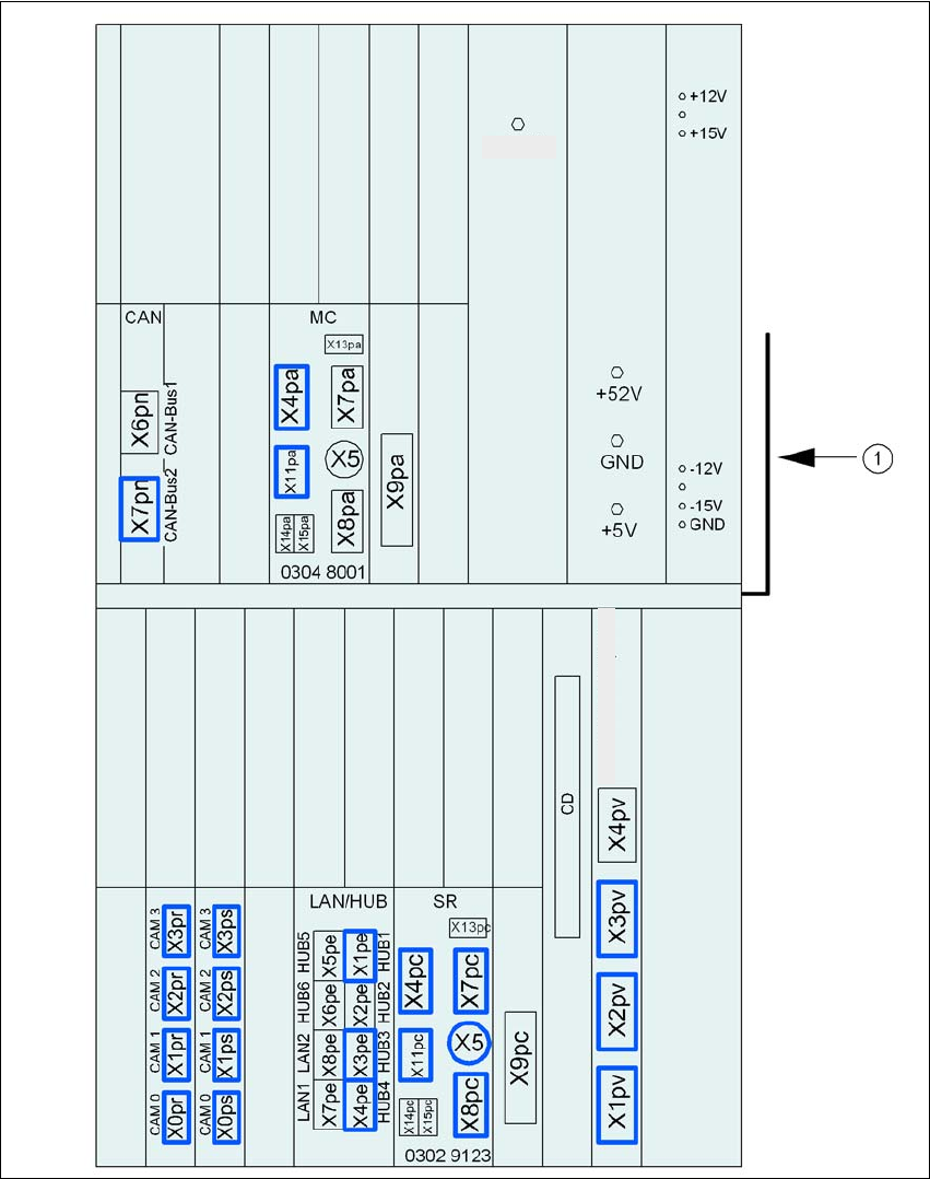
4.3.12 Installing the computer unit
4.3.12.1 Computer unit - Electrical connection points
4
Fig. 4.3 - 18 Computer unit, front panel - Connecting the plugs
(1) Cable guide plate
+3.3V
Video multiplexer .
User Manual SIPLACE D3 4 Setting up and commissioning
From software version SR.605.xx 07/2008 EN Edition 4.3 Setting up the machine
227
4
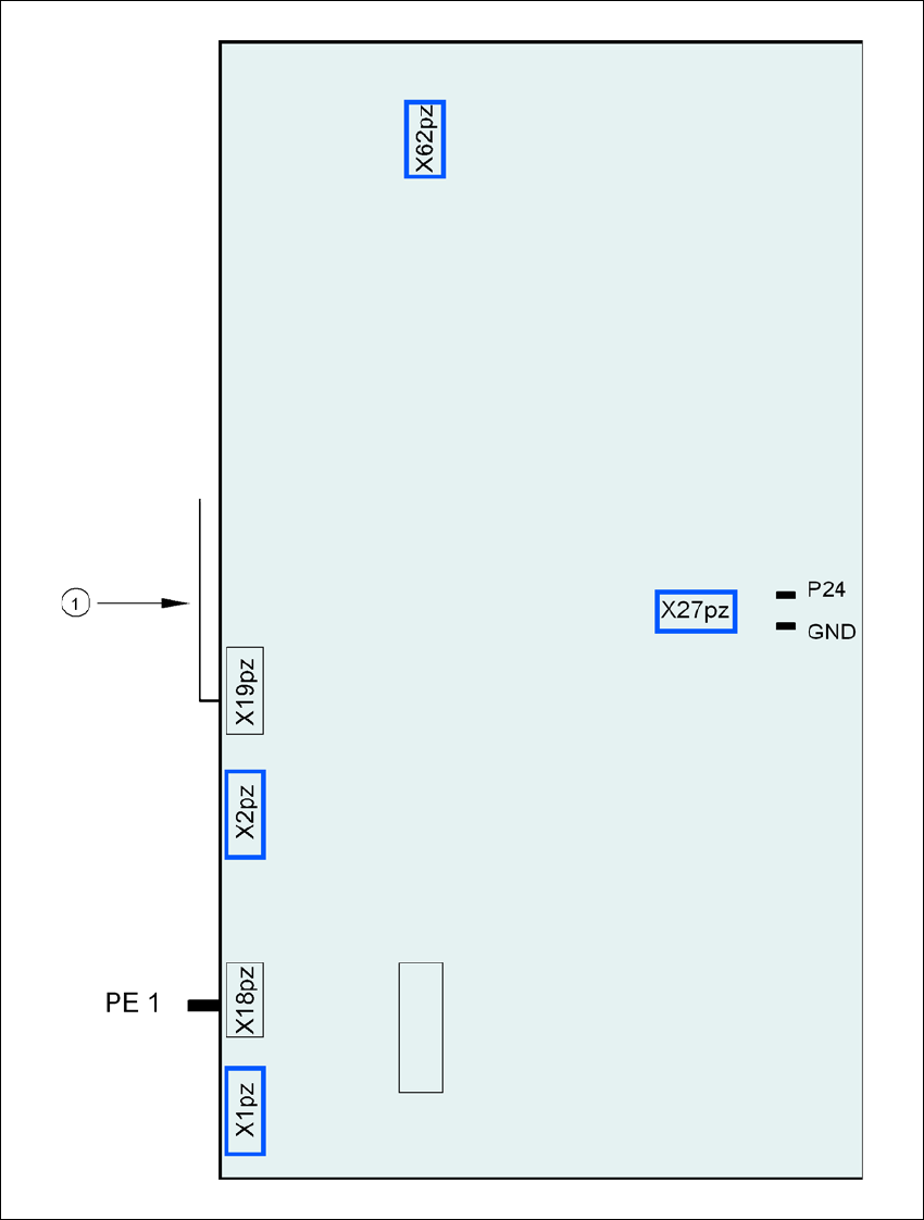
Fig. 4.3 - 19 Computer unit, back panel - Connecting the plugs
(1) Cable guide plate
Fan
Battery
+3.6V