00195760-0102_UM_D3_SR605_EN.pdf - 第230页
4 Setting up and commissioning User Manual SIPLACE D3 4.3 Setting up the machine From software version SR.605.xx 07/2008 EN Edition 230 4.3.13 Inst alling th e axis unit 4.3.13.1 Axis unit (gantry 1 and gantry 4) - Elect…

User Manual SIPLACE D3 4 Setting up and commissioning
From software version SR.605.xx 07/2008 EN Edition 4.3 Setting up the machine
229
4.3.12.3 Computer unit - plug-in connectors on the back panel
4
4
4.3.12.4 Fitting the computer unit
→ Plug in the plug-in connectors on the back panel of the computer unit (see Section 4.3.12.3).
→ Carefully lift the computer unit onto the rail in the extension kit.
→ Make sure that you do not squash any cables.
→ Check that the cables for the front panel are in the lateral cable routing plate
(item 1 in Fig. 4.3 - 18
, page 226).
→ Fix the cables to the front panel with cable ties.
→ Push the computer unit into the extension kit as far as the stop.
→ Connect the fan cable to the computer unit cable.
→ Plug in the plug-in connectors on the front panel of the computer unit (see Section 4.3 - 16
,
page 222
).
→ Secure the computer unit with the fillister head screw.
→ Fix the grounding cable to the doors (item 2 in Fig. 4.3 - 13
, page 217),
as shown in Fig. 4.3 - 14
on page 220.
→ Lock the doors.
Computer unit,
back panel
(Fig. 4.3 - 19
)
Plug
Connecting cable PLEASE NOTE
Plug Cable
PE1 Cable ring Grounding cable
Fix as shown in Fig. 4.3 - 14
,
page 220
.
X27pz X27pz 03003437 W1-W2 Insert as far as the stop
X2pz X2pz 03002966 W1-W5 Fix with screws
X1pz X1pz 03002969 W1-W5 Fix with screws
X62pz X62pz 03002488 Snap into place
P24 / GND X1 Fan in extension kit Insert as far as the stop
4 Setting up and commissioning User Manual SIPLACE D3
4.3 Setting up the machine From software version SR.605.xx 07/2008 EN Edition
230
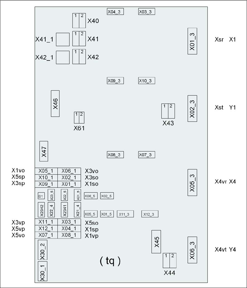
4.3.13 Installing the axis unit
4.3.13.1 Axis unit (gantry 1 and gantry 4) - Electrical connection points
4
Fig. 4.3 - 20 Axis unit (gantry 1 and gantry 4), back panel - Connecting the plugs
Plug
Plug
Plug

User Manual SIPLACE D3 4 Setting up and commissioning
From software version SR.605.xx 07/2008 EN Edition 4.3 Setting up the machine
231
4.3.13.2 Axis unit (gantry 1 and gantry 4) - Connecting the plugs
→ Connect the power cable as shown in the following diagram:
4
Axis unit, plugs Connecting cable PLEASE NOTE
Plug Cable
X41_1tq X41_1tq 03050919 Snap connector into place
X42_1tq X42_1tq 03050919 Snap connector into place
X45tq X45tq 03050920-W1 Snap connector into place
X46tq X46tq
03050920-W2
03050920-W3
Snap connector into place
X47tq X47tq
03050920-W4
03050920-W5
Snap connector into place
X01_3tq X4sr 03050881 Snap connector into place
X02_3tq X4st 03050882 Snap connector into place
X05_3tq X4vr 03050911 Snap connector into place
X06_3tq X4vt 03050912 Snap connector into place
X01_1tq X1so 03009771 Insert as far as the stop
X02_1tq X3so 03009772 Insert as far as the stop
X03_1tq X5so 03009773 Insert as far as the stop
X04_1tq X1sp 03009774 Insert as far as the stop
X05_1tq X1vo 03009831 Insert as far as the stop
X06_1tq X3vo 03009832 Insert as far as the stop
X07_1tq X5vo 03009833 Insert as far as the stop
X08_1tq X1vp 03009834 Insert as far as the stop
X09_1tq X3sp 03009775 Insert as far as the stop
X10_1tq X5sp 03009776 Insert as far as the stop
X11_1tq X3vp 03009835 Insert as far as the stop
X12_1tq X5vp 03009836 Insert as far as the stop
X03_3tq X03_3tq 03050883 Snap connector into place
X04_3tq X04_3tq 03050884 Snap connector into place
X07_3tq X07_3tq 03050913 Snap connector into place
X08_3tq X08_3tq 03050914 Snap connector into place