00195760-0102_UM_D3_SR605_EN.pdf - 第246页
4 Setting up and commissioning User Manual SIPLACE D3 4.4 Adapting the component trolley to the PCB conveyor height From software ver sion SR.605.xx 07/2008 EN Edition 246 4.4 Adapting the component trolley to the PCB co…
User Manual SIPLACE D3 4 Setting up and commissioning
From software version SR.605.xx 07/2008 EN Edition 4.3 Setting up the machine
245
4
4
4
4
4
4
4
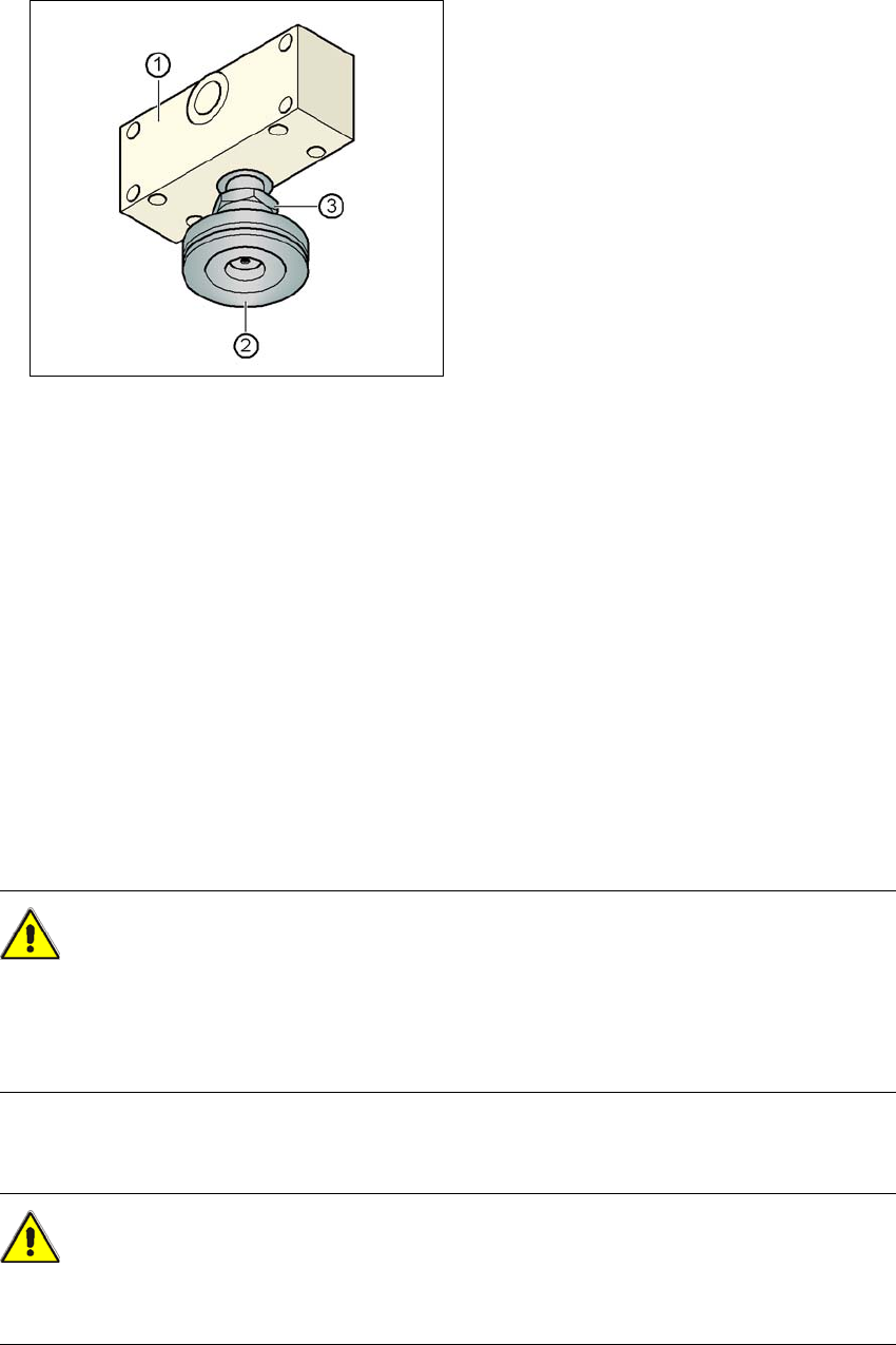
Fig. 4.3 - 32 Aligning and locking the middle machine foot
(1) Spacer
(2) Middle machine foot
(3) M24 lock nut
4
→ Use the spirit level to ensure that the machine is precisely aligned.
→ Use the size 65 open-ended spanner to tighten the M24 lock nut (item 3).
4.3.19 Removing the shipping braces
Remove all the shipping braces from the gantry axes.
4.3.20 Removing the corrosion protection from the guide rails
The machines were given a corrosion protection treatment before they were delivered.
CAUTION 4
– You should therefore remove the corrosion protection from all the axes and bearings when
you traverse the machine axes for the first time during commissioning.
– Grease all the axes and bearings with the grease described in the maintenance instructions.
If the corrosion protection agent is mixed with the bearing grease on the axes this can greatly re-
duce the service life of the bearings and guide rails.
CAUTION 4
Do not allow any alcohol to enter the guide carriages when you clean the guide rails and scale
rods. Alcohol will damage the bearing grease in the guide carriages.

4 Setting up and commissioning User Manual SIPLACE D3
4.4 Adapting the component trolley to the PCB conveyor height From software version SR.605.xx 07/2008 EN Edition
246
4.4 Adapting the component trolley to the PCB conveyor
height
The component trolley for the S feeder modules can be set to the following PCB conveyor heights
with just a few simple actions:
830 mm ± 15 mm (standard height)
900 mm ± 15 mm
930 mm ± 15 mm
950 mm ± 15 mm (SMEMA height) 4
4.4.1 Warning instructions
WARNING 4
Only SIPLACE engineers or qualified personnel are permitted to adjust the component trolley
height.
→ Always follow the applicable accident prevention regulations.
→ Remove all the feeder modules from the component table bed if you want to adjust the height
of the component table.
4.4.2 Tools and equipment
You will need the following tools and equipment to adjust the height of the component trolley:
–Hammer
– Punch, 8 mm
– Eye-bolt with M12 thread for lifting the component trolley table,
DIN 580 M12-St, item no. 00048350-xx
– Lifting device for raising the component trolley table, carrying capacity at least 80 kg
User Manual SIPLACE D3 4 Setting up and commissioning
From software version SR.605.xx 07/2008 EN Edition 4.4 Adapting the component trolley to the PCB conveyor height
247
4
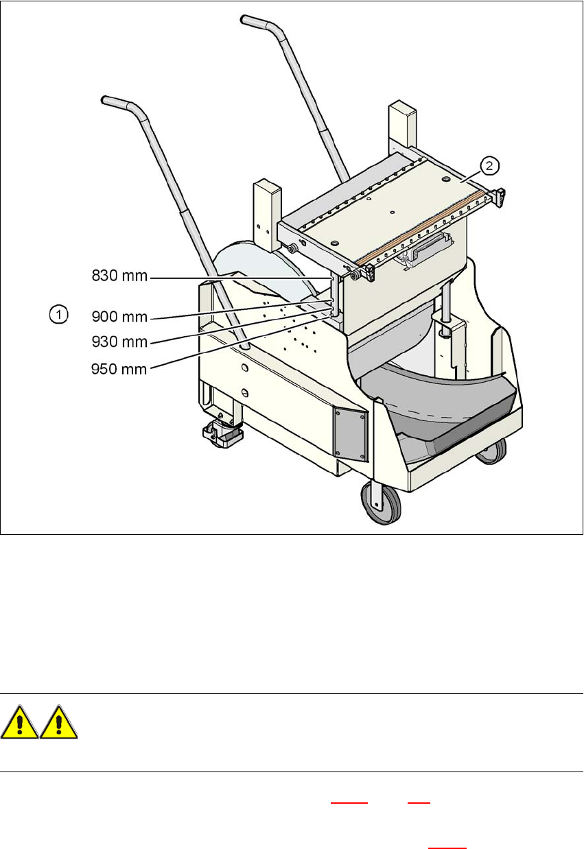
Fig. 4.4 - 1 Component trolley with a PCB conveyor height of 950 mm
(1) Holes in the guide columns for the conveyor heights of 830 to 950 mm
(2) Component trolley table
4.4.3 Changing the component trolley height
WARNING 4
Remove all the feeder modules from the component trolley table bed.
→ Screw the eye-bolt into the M12 hole (item 1 in Fig. 4.4 - 2
, page 248) in the component trolley
table bed.
→ Attach the hooks of the lifting device to the eye-bolt (item 2 in Fig. 4.4 - 2
).