00195760-0102_UM_D3_SR605_EN.pdf - 第248页
4 Setting up and commissioning User Manual SIPLACE D3 4.4 Adapting the component trolley to the PCB conveyor height From software ver sion SR.605.xx 07/2008 EN Edition 248 → Raise the component trolley be d slightly to e…
User Manual SIPLACE D3 4 Setting up and commissioning
From software version SR.605.xx 07/2008 EN Edition 4.4 Adapting the component trolley to the PCB conveyor height
247
4
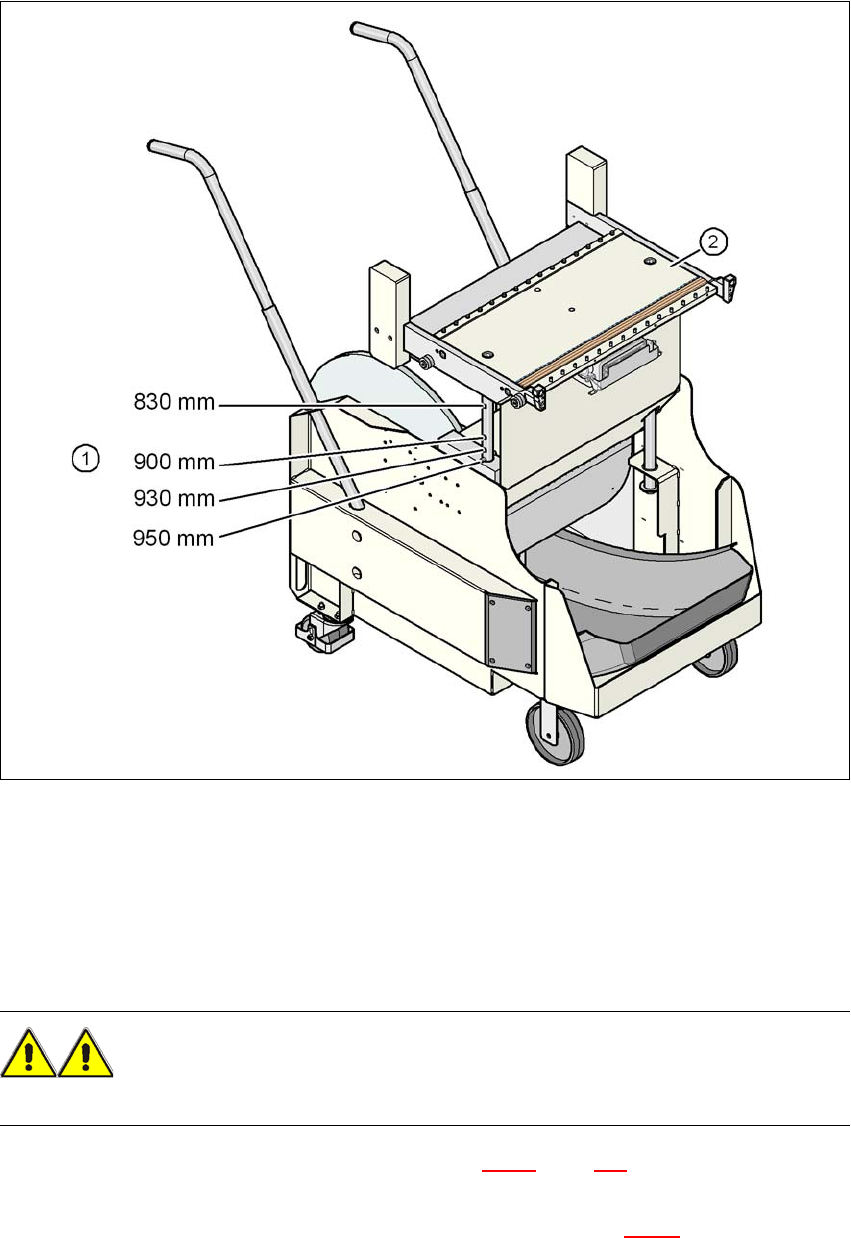
Fig. 4.4 - 1 Component trolley with a PCB conveyor height of 950 mm
(1) Holes in the guide columns for the conveyor heights of 830 to 950 mm
(2) Component trolley table
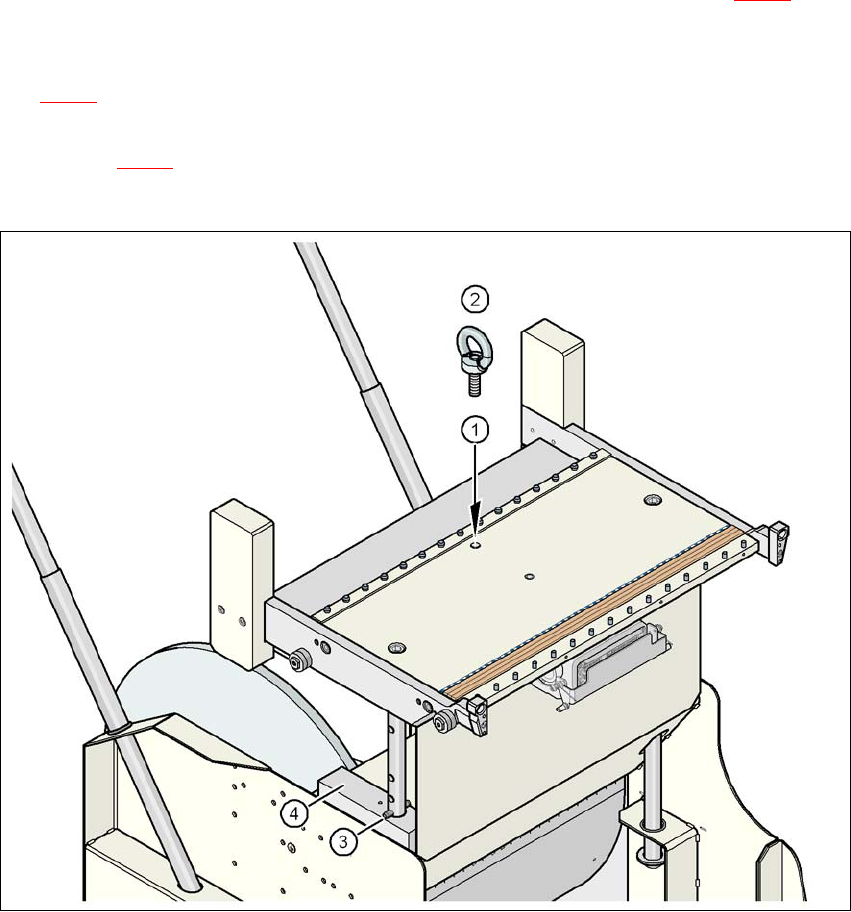
4.4.3 Changing the component trolley height
WARNING 4
Remove all the feeder modules from the component trolley table bed.
→ Screw the eye-bolt into the M12 hole (item 1 in Fig. 4.4 - 2
, page 248) in the component trolley
table bed.
→ Attach the hooks of the lifting device to the eye-bolt (item 2 in Fig. 4.4 - 2
).
4 Setting up and commissioning User Manual SIPLACE D3
4.4 Adapting the component trolley to the PCB conveyor height From software version SR.605.xx 07/2008 EN Edition
248
→ Raise the component trolley bed slightly to expose the split pins (item 3 in Fig. 4.4 - 2).
→ Use the punch to carefully tap out the split pins on both sides.
→ Insert the spiral clamping pins into the holes for the required PCB conveyor height (see Fig.
4.4 - 1
).
→ Lower the component trolley bed slowly until the split pins lie on the supporting blocks (item
4 in Fig. 4.4 - 2
).
→ Unscrew the eye-bolt from the component trolley table.
4
Fig. 4.4 - 2 Position of the eye-bolt on the component trolley
(1) M12 hole for eye-bolt
(2) Eye-bolt, DIN 580 M12-St
(3) Spiral clamping pin, DIN 7343, 8x40 - St, 2x
(4) Supporting block, 2x
User Manual SIPLACE D3 4 Setting up and commissioning
From software version SR.605.xx 07/2008 EN Edition 4.5 Adapting the used tape channel
249
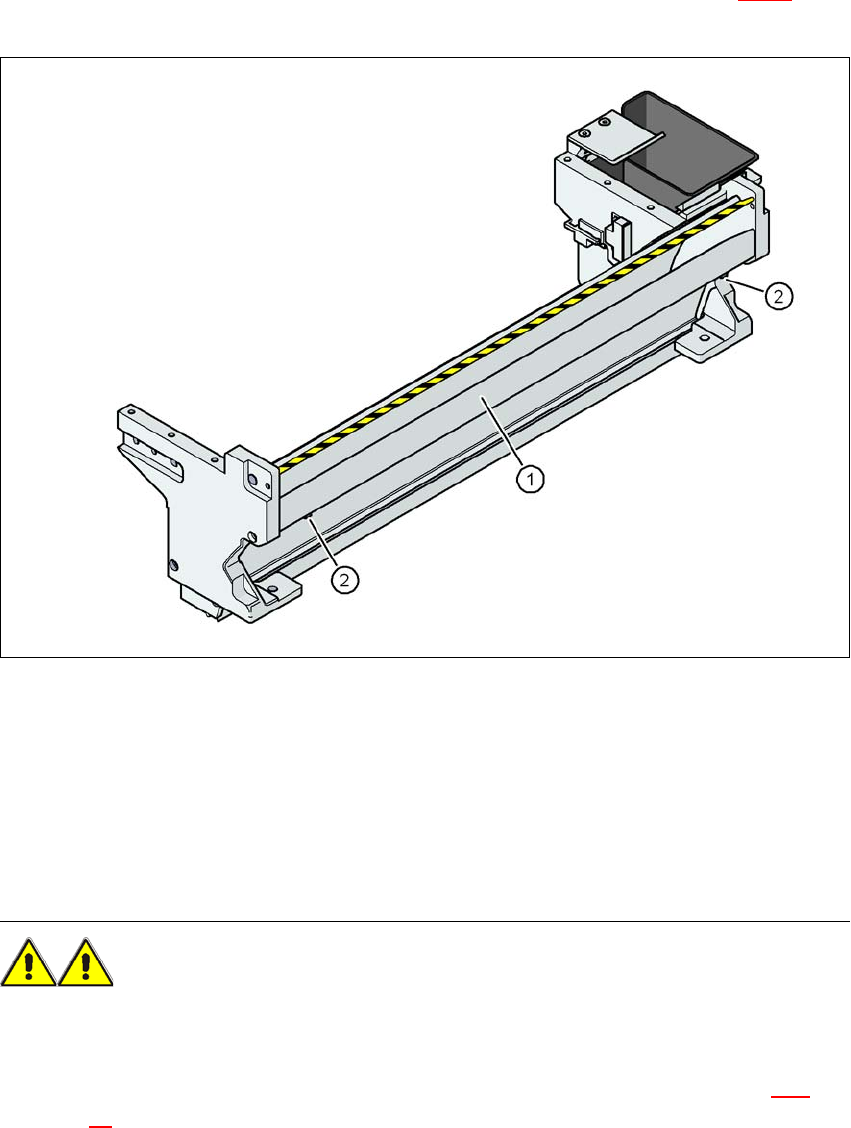
4.5 Adapting the used tape channel
If feeder modules that process component tapes with a pocket height > 17 mm are used, such as,
for example, the 44 mm S DP feeder module, then the separating plate (item 3 in Fig. 4.5 - 1
) must
be removed.
4
Fig. 4.5 - 1 Used tape channel with component reject bin
(1) separating plate for tapes > 17 mm, removable
(2) DIN 84 - M3x6 screw, 2x
4
4
4.5.1 Safety instructions
WARNING 4
→ Switch the machine off at the main switch to remove the dividing plate.
→ Disconnect the machine from the power and compressed air supply.
→ Secure the machine to prevent it being switched on again, as described in Section 2.10
,
page 90
.