00195760-0102_UM_D3_SR605_EN.pdf - 第283页
User Manual SIPLACE D3 6 Station extensions From software version SR.605.xx 07/2008 EN Edition 6.1 Nozzle changer 283 6.1.1.3 Position of the nozzle changers for the C&P12 head 1 or 2 nozzle changers m ay be installe…

6 Station extensions User Manual SIPLACE D3
6.1 Nozzle changer From software version SR.605.xx 07/2008 EN Edition
282
6.1.1.1 Description
This nozzle changer can hold up to 5 magazines, each with 12 nozzle holders. The magazines
are seated on a common support. They are centered using two parallel pins and fixed in place with
clips.
6.1.1.2 Technical data
6
Nozzle changer for the 12-segment Collect&Place head
Dimensions (length x width x height) 449 x 62.7 x 77.7 mm³
Number of nozzle holders 60
Nozzle types 9xx
Nozzle changeover time approx. 2s per nozzle
Compressed air connection 0.48 MPa (4.8 bar)
User Manual SIPLACE D3 6 Station extensions
From software version SR.605.xx 07/2008 EN Edition 6.1 Nozzle changer
283
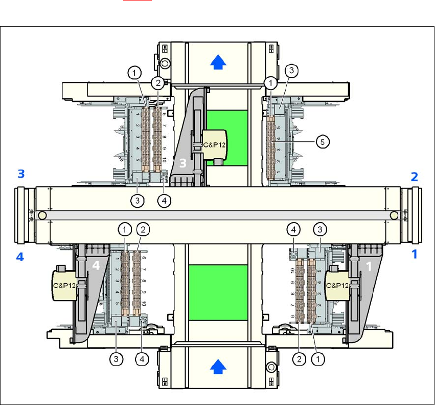
6.1.1.3 Position of the nozzle changers for the C&P12 head
1 or 2 nozzle changers may be installed at locations 1, 3 and 4 for the 12-segment Collect&Place
head (items 1 and 2 in Fig. 6.1 - 2
). This gives a total capacity of 7 nozzle changers with 35 mag-
azines and a total of 420 nozzle holders.
6
Fig. 6.1 - 2 Position of the nozzle changers for the 12-segment Collect&Place head
6
(1) Nozzle changer, "row 1"
(2) Nozzle changer, "row 2"
(3) Reject bin for components
(4) Take-off device and reject bin for nozzles
(5) Nozzle magazine
6 Station extensions User Manual SIPLACE D3
6.1 Nozzle changer From software version SR.605.xx 07/2008 EN Edition
284
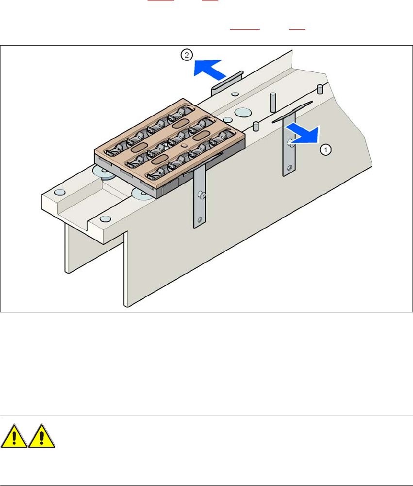
6.1.1.4 Assembly
"Row 1" nozzle changers (see Fig. 6.1 - 2, page 283) are each fixed to the component trolley dock-
ing unit. There is an additional assembly kit for the "row 2" nozzle changer. This kit consists of the
take-off device and the nozzle reject bin (see Section 6.1.1.8
, page 288).
6
Fig. 6.1 - 3 Assembly position
(1) Spring hook pointing toward the operator
(2) Retaining clamp pointing toward the PCB conveyor
→ Align the nozzle changer so that the moving spring hooks always point toward the operator,
while the retaining clamps always point toward the PCB conveyor.
WARNING 6
Only install the associated nozzle changer for each placement head. There is a risk of head
crashes with mixed configurations.