00195760-0102_UM_D3_SR605_EN.pdf - 第284页
6 Station extensions User Manual SIPLACE D3 6.1 Nozzle changer From software version SR.605.xx 07/2008 EN Edition 284 6.1.1.4 Assembly "Row 1" no zzle changers (see Fig. 6.1 - 2 , page 283 ) are each fixed to t…
User Manual SIPLACE D3 6 Station extensions
From software version SR.605.xx 07/2008 EN Edition 6.1 Nozzle changer
283
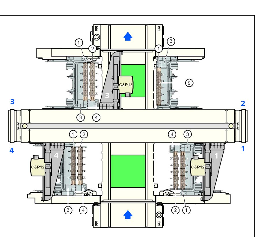
6.1.1.3 Position of the nozzle changers for the C&P12 head
1 or 2 nozzle changers may be installed at locations 1, 3 and 4 for the 12-segment Collect&Place
head (items 1 and 2 in Fig. 6.1 - 2
). This gives a total capacity of 7 nozzle changers with 35 mag-
azines and a total of 420 nozzle holders.
6
Fig. 6.1 - 2 Position of the nozzle changers for the 12-segment Collect&Place head
6
(1) Nozzle changer, "row 1"
(2) Nozzle changer, "row 2"
(3) Reject bin for components
(4) Take-off device and reject bin for nozzles
(5) Nozzle magazine
6 Station extensions User Manual SIPLACE D3
6.1 Nozzle changer From software version SR.605.xx 07/2008 EN Edition
284
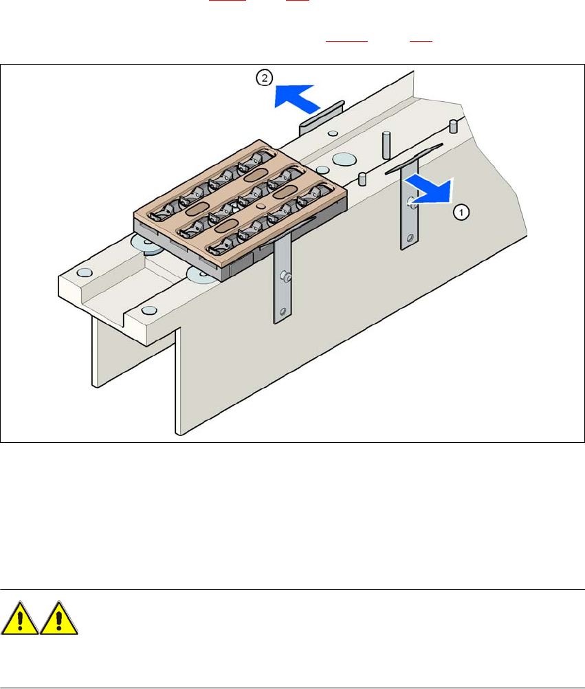
6.1.1.4 Assembly
"Row 1" nozzle changers (see Fig. 6.1 - 2, page 283) are each fixed to the component trolley dock-
ing unit. There is an additional assembly kit for the "row 2" nozzle changer. This kit consists of the
take-off device and the nozzle reject bin (see Section 6.1.1.8
, page 288).
6
Fig. 6.1 - 3 Assembly position
(1) Spring hook pointing toward the operator
(2) Retaining clamp pointing toward the PCB conveyor
→ Align the nozzle changer so that the moving spring hooks always point toward the operator,
while the retaining clamps always point toward the PCB conveyor.
WARNING 6
Only install the associated nozzle changer for each placement head. There is a risk of head
crashes with mixed configurations.

User Manual SIPLACE D3 6 Station extensions
From software version SR.605.xx 07/2008 EN Edition 6.1 Nozzle changer
285
6.1.1.5 Notes on operation
→ When you fill a magazine with a certain nozzle type for the first time, attach an adhesive label
to identify the type.
PLEASE NOTE 6
Fill the magazines off the machine and always replace complete magazines. 6
→ Open the locking plate and place the nozzles in the nozzle holders.
→ Close the locking plate so that the nozzles cannot drop out of the magazines.
CAUTION 6
Before you fill magazine, make sure that all the nozzles on the Collect&Place head have
been returned to their magazines. 6
→ Programming the nozzle changer is described in the SIPLACE Pro user manual.
PLEASE NOTE 6
→ Do not allow components to drop onto the magazines. If they do, they could jam the locking
plate.
→ Do not allow components to drop onto free feeder module locations. They will stick to the
magnetic bar. Production may have to be interrupted if the feeder modules are not placed on
the component table correctly. You should therefore regularly clean the magazines and free
locations.