00195760-0102_UM_D3_SR605_EN.pdf - 第295页
User Manual SIPLACE D3 6 Station extensions From software version SR.605.xx 07/2008 EN Edition 6.1 Nozzle changer 295 → First place the side of the magazine with the centering hole (item 3 in Fig. 6. 1 - 10 ) and the slo…
6 Station extensions User Manual SIPLACE D3
6.1 Nozzle changer From software version SR.605.xx 07/2008 EN Edition
294
6.1.2.6 Changing the magazine
→ To remove the magazine, press the spring hook (item 1) away from the magazine and lift the
magazine out of the base.
6
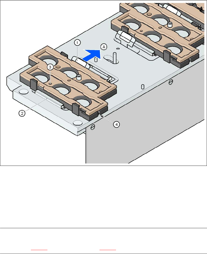
Fig. 6.1 - 10 Changing the magazine
(1) Spring hook
(2) Retaining clamp
(3) Centering hole
(4) Slot
(A) Push the spring hook away from the magazine
PLEASE NOTE
Make sure that you insert the magazine so that the centering pins slide into the centering hole
(item 3 in Fig. 6.1 - 10) and slot (item 4 in Fig. 6.1 - 10). 6
User Manual SIPLACE D3 6 Station extensions
From software version SR.605.xx 07/2008 EN Edition 6.1 Nozzle changer
295
→ First place the side of the magazine with the centering hole (item 3 in Fig. 6.1 - 10) and the
slot (item 4 in Fig. 6.1 - 10
) on the base. The two knobs on the magazine must slide into the
retaining clamp (item 2 in Fig. 6.1 - 10
).
→ Push the spring hook away from the magazine.
→ Press the magazine so that it lies flat on the base, then release the spring hook. The spring
hook must latch into place.
6.1.2.7 Position detection
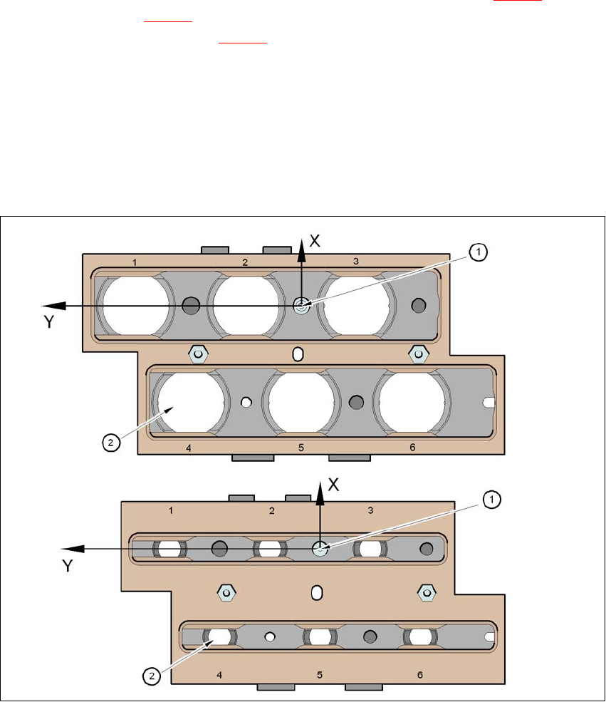
Every magazine of the nozzle changer has a positioning fiducial for position detection.
6
Fig. 6.1 - 11 Nozzle changer - Position detection
(1) Positioning fiducial
(2) Position of the nozzles in the magazine with respect to the positioning fiducial
6 Station extensions User Manual SIPLACE D3
6.1 Nozzle changer From software version SR.605.xx 07/2008 EN Edition
296
6.1.2.8 "Row 2" nozzle changer for the 6-segment Collect&Place head
Item no. 00119664-xx Nozzle changer 2, HF/X/D3, 6-segment C&P head
The "row 2" nozzle changer may be installed at the following locations:
Locations 1, 3 and 4 (see Fig. 6.1 - 8
, page 291)
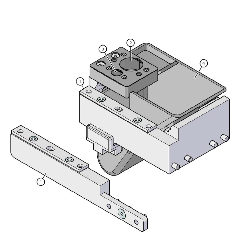
The retrofit package contains an assembly kit and a nozzle take-off device with reject bin, in ad-
dition to the nozzle changer.
6
Fig. 6.1 - 12 Assembly kit for the "row 2" nozzle changer
(1) Assembly kit for the "row 2" nozzle changer
(2) Nozzle take-off device for type 8xx nozzles
(3) Nozzle take-off device for type 9xx nozzles
(4) Nozzle reject bin