00195760-0102_UM_D3_SR605_EN.pdf - 第302页
6 Station extensions User Manual SIPLACE D3 6.2 Matrix tray changer From software version SR.605.xx 07/2008 EN Edition 302 6.2 Matrix tray changer Item no. 001 16438-xx SIPLACE matrix tray changer (MTC) 6.2.1 Safety inst…
User Manual SIPLACE D3 6 Station extensions
From software version SR.605.xx 07/2008 EN Edition 6.1 Nozzle changer
301
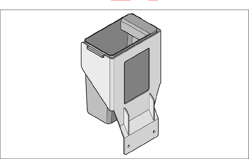
6.1.3.7 Component reject bin
A component reject bin may be installed for the SIPLACE TwinHead. This is positioned beside the
fine-pitch vision module (see item 4 in Fig. 6.1 - 14
, page 298).
6
Fig. 6.1 - 17 Component reject bin
6.1.3.8 Grippers and special nozzles
The SIPLACE machines can process components based on through hole technology and odd-
shaped (OSC) components, in addition to the standard SMT spectrum. SIPLACE also contin-
uously develops special nozzles and grippers in parallel.
Special nozzles are available for all placement heads in order to process placement jobs with max-
imum speed, precision and flexibility. The use of automatic nozzle changers also reduces the set-
up times that occur at a product change.
SIPLACE can provide mechanical grippers for Pick&Place heads. If a component's surface is
not suitable for sucking up with nozzles, then it can be picked up and placed with mechanical grip-
pers. There are two types of gripper, and their functions can be divided into two groups:
– Grippers that grip the component at its outer edges and
– Grippers that grip the component at its inner edge.
Information on special nozzles and grippers is available from SIPLACE. Fo
r the production of
spec
ial magazines and grippers, again contact SIPLACE.
6 Station extensions User Manual SIPLACE D3
6.2 Matrix tray changer From software version SR.605.xx 07/2008 EN Edition
302
6.2 Matrix tray changer
Item no. 00116438-xx SIPLACE matrix tray changer (MTC)
6.2.1 Safety instructions
WARNING 6
→ Never reach into the gaps between the matrix tray changer and the machine base while the
machine is running.
→ The power supply cable must not be plugged into or unplugged from the external power supply
unless the matrix tray changer is docked into the machine.
→ The matrix tray changer must NOT be operated unless it is docked into the machine.
6.2.2 Description
The matrix tray changer can be used to store and change up to 100 waffle-pack trays fully auto-
matically. The levels (storage locations in the tray supplies) for the waffle-pack trays are numbered
consecutively in ascending order from bottom to top.
The tray supplies move independently of one another in the vertical direction until the selected
magazine is within range of the feed axis. The horizontal feed axis transports the waffle-pack tray
from the tray supply into the access area of the placement head.
Tray supply 1 has 30 levels, each of which can hold 2 JEDEC trays or one large tray up to 240 x
340 mm² from the waffle-pack tray carriers.
Tray supply 2 has a capacity of 40 levels for JEDEC trays.
The matrix tray changer has an integral chassis, and is therefore easy to move to other locations.
It is supplied with the PCB conveyor height implemented for the machines, but can be adapted for
the 830, 900, 930 and 950 mm PCB conveyor heights with just a few simple operations.

User Manual SIPLACE D3 6 Station extensions
From software version SR.605.xx 07/2008 EN Edition 6.2 Matrix tray changer
303
6.2.3 Technical data
6.2.3.1 Dimensions, weight, other data
6
Tray supply 1 (XL) Tray supply 2
Dimensions
Length x width
Height
1305 x 600 mm²
1490 mm for 830 mm PCB conveyor height
1560 mm for 900 mm PCB conveyor height
1590 mm for 930 mm PCB conveyor height
1610 mm for 950 mm PCB conveyor height
Weight (basic equipment)
Approx. 500 kg (with cassettes and waffle-pack tray
carriers)
Weight (fully equipped) Approx. 534 kg (with components)
Weight (moving mass) Approx. 80 kg Approx. 43.5 kg
Cassette size (L x W x H) 391.2 x 305.6 x 93.3 mm³ 352.7 x 154.8 x 133.8 mm³
Cassette weight
(fully equipped)
(without waffle-pack tray carrier)
Approx. 11 kg
Approx. 1.7 kg
Approx. 7.5 kg
Approx. 1.35 kg
Weight of the
waffle-pack tray carrier
850 g 150 g
Dimensions of the
waffle-pack tray carrier (L x W x H) 386.5 x 295.8 x 11.1 mm³ 371 x 146 x 10.1 mm³
Spacing from one cassette to next 96 mm 135 mm
Distance from level to level 12 mm 11.8 mm
Vertical travel 444 mm (1st to 30th WTC
a
) 511.2 mm (1st to 40th WTC
a
)
Horizontal travel between outgoing
and pick-up position Approx. 647 mm Approx. 638 mm
Storage capacity 30 XL waffle-pack tray carri-
ers with 60 JEDEC or
30 special magazines
of maximum size
40 waffle-pack tray carriers
with 40 JEDEC
waffle-pack trays
Changeover time (over 5 levels) Approx. 2 s Approx. 1.5 s
Max. height of component and waf-
fle-pack tray, including tolerances
All levels filled
One level free
Two levels free
8.5 mm
19.5 mm
31.5 mm
8.5 mm
19.5 mm
-
a) Waffle-pack tray carrier