00195760-0102_UM_D3_SR605_EN.pdf - 第315页
User Manual SIPLACE D3 6 Station extensions From software version SR.605.xx 07/2008 EN Edition 6.6 Component camera for the TwinHead, FC camera 315 6.6 Component camera for the T winHead, FC camera 6.6.1 St ationary P&am…

6 Station extensions User Manual SIPLACE D3
6.4 Sensor for the component reject bin From software version SR.605.xx 07/2008 EN Edition
314
6.4 Sensor for the component reject bin
Item no. 00116848-xx Sensor, component reject bin, X-series/D3
The sensor for the component reject bin monitors whether the reject bin is seated correctly in its
mount.
– If the reject bin was not inserted correctly, the machine cannot be started.
– If the reject bin jumps out of its mount during the placement process, the machine is stopped
immediately to avoid a head crash.
Each reject bin can be monitored by a separate sensor.
6.5 SIPLACE High-Force Head
Item no. 00119878-xx High-Force Head for D3
This item number only applies when a new placement machines is ordered with a High-Force
Head rather than a standard TwinHead. 6
Item no. 00119753-xx High-Force Head upgrade kit
Use this item number if you want to replace a standard TwinHead with a High-Force Head.6
6.5.1 Description
The SIPLACE High-Force Head is a development offshoot of the standard TwinHead. It can pro-
cess the same component range and also offers the possibility of achieving set-down forces up to
30 N.
Otherwise the technical data for the TwinHead and High-Force Head is the same (see Section
3.5.3.2
, page 116).
All the nozzles and grippers that are used with the standard TwinHead can be used for the SI-
PLACE High-Force Head.
Programmable set-down force 2.0 N to 10 N ± 10%
greater than 10 N up to 30 N ± 15%
User Manual SIPLACE D3 6 Station extensions
From software version SR.605.xx 07/2008 EN Edition 6.6 Component camera for the TwinHead, FC camera
315
6.6 Component camera for the TwinHead, FC camera
6.6.1 Stationary P&P component camera (type 25) 16 x 16, digital (FC camera)
Item no. 00119718-xx Component camera, stationary 16 x 16, digital, type 25
6
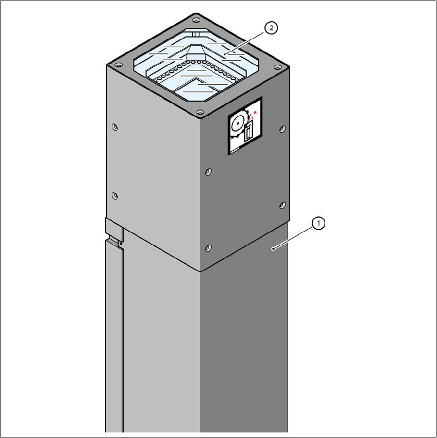
Fig. 6.6 - 1 Stationary P&P component camera (type 25) 16 x 16, digital (FC camera)
(1) Camera housing with integral camera and camera amplifier
(2) Glass plate - over the illumination and lens levels
6
6 Station extensions User Manual SIPLACE D3
6.6 Component camera for the TwinHead, FC camera From software version SR.605.xx 07/2008 EN Edition
316
6.6.2 Safety instructions
WARNING 6
When the placement head is changed from the TwinHead to the Collect&Place head, the Twin-
Head's component cameras (stationary, P&P, type 33, 55 x 45, and type 25, 16 x 16) must be
removed, otherwise the Collect&Place head will collide with the camera housings.
6.6.3 Technical data
6
6
6
6
6.6.4 Position of the stationary component cameras
The position of the stationary component cameras and the associated configurations are de-
scribed in Section 3.8.2
, from page 134.
Component dimensions 0.2 x 0.2 mm² up to 16 x 16 mm² for single component measurement
Range of components 0201 to SO, PLCC, QFP, sockets, plugs, BGA, special components,
bare dies, flip-chips, shields
Min. lead pitch 0.25 mm
Min. lead width 0.1 mm
Min. ball pitch 0.14 mm
Min. ball diameter 0.08 mm
Field of vision 19.4 x 19.4 mm²
Method of illumination Front-illumination (6 levels, programmable as required)