00195760-0102_UM_D3_SR605_EN.pdf - 第317页
User Manual SIPLACE D3 6 Station extensions From software version SR.605.xx 07/2008 EN Edition 6.7 PCB barcode scanner 317 6.7 PCB barcode scanner Item no. 001 19682-xx 1D PCB barcode scanner Item no. 001 19679-xx 2D PCB…
6 Station extensions User Manual SIPLACE D3
6.6 Component camera for the TwinHead, FC camera From software version SR.605.xx 07/2008 EN Edition
316
6.6.2 Safety instructions
WARNING 6
When the placement head is changed from the TwinHead to the Collect&Place head, the Twin-
Head's component cameras (stationary, P&P, type 33, 55 x 45, and type 25, 16 x 16) must be
removed, otherwise the Collect&Place head will collide with the camera housings.
6.6.3 Technical data
6
6
6
6
6.6.4 Position of the stationary component cameras
The position of the stationary component cameras and the associated configurations are de-
scribed in Section 3.8.2
, from page 134.
Component dimensions 0.2 x 0.2 mm² up to 16 x 16 mm² for single component measurement
Range of components 0201 to SO, PLCC, QFP, sockets, plugs, BGA, special components,
bare dies, flip-chips, shields
Min. lead pitch 0.25 mm
Min. lead width 0.1 mm
Min. ball pitch 0.14 mm
Min. ball diameter 0.08 mm
Field of vision 19.4 x 19.4 mm²
Method of illumination Front-illumination (6 levels, programmable as required)

User Manual SIPLACE D3 6 Station extensions
From software version SR.605.xx 07/2008 EN Edition 6.7 PCB barcode scanner
317
6.7 PCB barcode scanner
Item no. 00119682-xx 1D PCB barcode scanner
Item no. 00119679-xx 2D PCB barcode scanner
Item no. 00119684-xx PCB barcode scanner assembly kit
6.7.1 Description
The PCB barcode scanner is used to automatically record and decode barcodes on PCBs. The
PCB barcode scanner sends the read data via its serial interface to the transport controller and
then for further processing to the machine controller via the CAN bus.
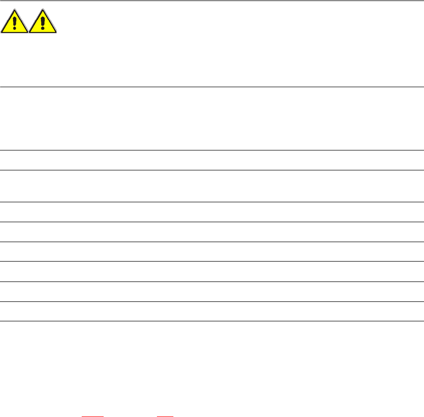
Fig. 6.7 - 1 PCB barcode block diagram
6
The PCB barcode scanners are installed on the input side of the placement machine on the PCB
conveyor. Up to four devices can be retrofitted to each machine. The barcode scanners are fitted
so that the barcode labels on the topside and underside of the PCBs can be scanned on both
tracks of the dual conveyor.
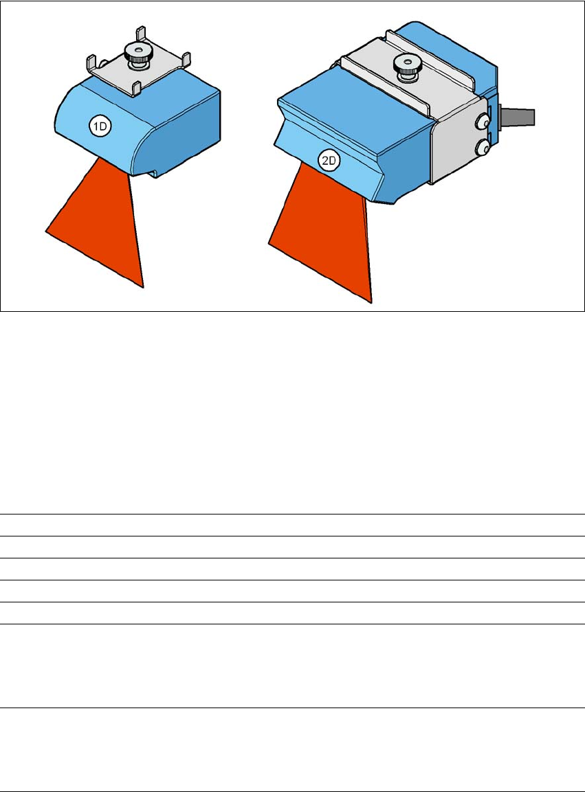
There are two variants of the barcode scanner:
– 1D barcode scanner
This barcode scanner processes barcodes. 6
– 2D barcode scanner
Device number
1
Barcode
scanner
top
Distribution
board
Transport
controller,
right
Barcode
scanner
bottom
2
3
Barcode
scanner
top
Distribution
board
Transport
controller,
left
Barcode
scanner
bottom
4
Machine
controller
Control
computer
SIPLACE Pro
computer
LANCAN busV-24V-24
6 Station extensions User Manual SIPLACE D3
6.7 PCB barcode scanner From software version SR.605.xx 07/2008 EN Edition
318
This barcode scanner processes matrix code. Matrix code is primarily used when there is
not enough space for barcode labels. The 2D barcode scanner also reads conventional bar-
codes. 6
6
Fig. 6.7 - 2 1D and 2D barcode scanners
The PCB barcode scanners are fixed to the top and bottom profiled rail using retainers. These can
be positioned as required on the profiled rails, and aligned with respect to the barcode labels. De-
pending on the position of the barcode strips, the barcode scanner can be attached in a few simple
steps so that the strips can be read parallel to or across the PCB transport direction.
6.7.2 Technical data – 1D barcode scanner
6
Laser diode Red light
Wave length 670 nm
Laser class Class 2, as per DIN EN 60825-1:2001
Scanning frequency 400 ... 1200 Hz
Resolution 0.15 mm ... 0.5 mm
Code types Code 39, Code 128, Code 93,
Codabar, EAN, EAN 128, UPC,
2/5 Interleaved, Pharma Code
(others available on request)
Barcode length
Single conveyor
Dual conveyor, asynchronous
Dual conveyor, synchronous
Max. 40 characters
Max. 40 characters
Max. 40 characters