00195760-0102_UM_D3_SR605_EN.pdf - 第328页
6 Station extensions User Manual SIPLACE D3 6.12 Magnetic pin support From software version SR.605.xx 07/2008 EN Edition 328 6.12 Magnetic pin support Item no. 001 19680-xx Magnetic pin support HS/HF/X/D series Wide boar…

User Manual SIPLACE D3 6 Station extensions
From software version SR.605.xx 07/2008 EN Edition 6.11 Long board
327
6.11 Long board
Item no. 00119672-xx Stopper, Long board option - SIPLACE HF/X/D3
Item no. 00119629-xx Conveyor width 250/508 mm (Wide board), X-series/D3
Item no. 00119631-xx Conveyor width 242/508 mm (Wide board), D1/D2/D3/D4
The following PCB formats can be placed on the machine:
We can supply the Long board option as a retrofit kit for placing PCBs that are over 450 mm long.
If the Long board option is installed, then the following PCB formats can be processed:
The retrofit kit consists of the following parts:
– Complete mechanism: stopper, sensors, cables and assembly parts
– Optional CD for enabling the function on the SIPLACE Pro computer
– Retrofit instructions
PLEASE NOTE 6
The Long board option must be ordered 2x for the dual conveyor.
More detailed information can be found in the Long board retrofit instructions,
item no. 00193888-01.
Single conveyor (standard width) 50 x 50 mm² to 450 x 450 mm²
Single conveyor, Wide board 50 x 50 mm² to 450 x 508 mm²
Dual conveyor (standard width) 50 x 50 mm² to 450 x 216 mm²
Dual conveyor, Wide board 50 x 50 mm² to 450 x 250 mm²
Dual conveyor in Single conveyor mode 50 x 50 mm² to 450 x 380 mm²
Dual conveyor in Single conveyor mode, Wide board 50 x 50 mm² to 450 x 450 mm²
Single conveyor, Long board (standard width) 50 x 80 mm² to 610 x 450 mm²
Single conveyor, Wide board 50 x 80 mm² to 610 x 508 mm²
Dual conveyor, Long board 50 x 80 mm² to 610 x 216 mm²
Dual conveyor, Wide board, Long board 50 x 80 mm² to 610 x 250 mm²
Dual conveyor in Single conveyor mode, Long board 50 x 80 mm² to 610 x 380 mm²
Dual conveyor in Single conveyor mode, Wide board, Long
board
50 x 80 mm² to 610 x 450 mm²
6 Station extensions User Manual SIPLACE D3
6.12 Magnetic pin support From software version SR.605.xx 07/2008 EN Edition
328
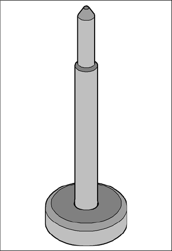
6.12 Magnetic pin support
Item no. 00119680-xx Magnetic pin support HS/HF/X/D series
Wide boards tend to deflect during placement such that, under certain circumstances, the compo-
nents can no longer be placed with the desired accuracy. Highly curved PCBs also affect the
placement accuracy. This problem can be easily rectified by fitting magnetic pin supports on the
lifting table.
6
Fig. 6.12 - 1 Magnetic pin support
User Manual SIPLACE D3 6 Station extensions
From software version SR.605.xx 07/2008 EN Edition 6.13 Feeder module cover flap
329
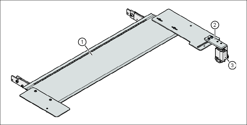
6.13 Feeder module cover flap
Item no. 00119610-xx Feeder module cover flap, HF/X/D3, for locations 2/4
Item no. 00119633-xx Feeder module cover flap, HF/X/D3, for locations 1/3
The feeder module cover flap is installed over the component feeder area. It is designed to prevent
a head crash with an upright feeder module retainer that has not been engaged correctly. The
feeder module cover flap can also prevent the front panel of feeder modules entering the place-
ment head traveling range due to incorrect operation.
6
Fig. 6.13 - 1 Feeder module cover flap for locations 1 and 3
(1) Feeder module cover flap
(2) Mechanical lock
(3) Switch in the EMERGENCY STOP circuit
The switch for the feeder module cover flap is looped into the EMERGENCY STOP circuit. The
feeder module cover flap must be locked mechanically, which causes the switch to close the open
EMERGENCY STOP circuit.