00195760-0102_UM_D3_SR605_EN.pdf - 第333页
User Manual SIPLACE D3 6 Station extensions From software version SR.605.xx 07/2008 EN Edition 6.15 Hi gh-resolution CO camera for the 12 -segment C&P head, type 29 333 6.15 High-resolution CO camera for the 12-segme…

6 Station extensions User Manual SIPLACE D3
6.14 Component sensor for the C&P12 head From software version SR.605.xx 07/2008 EN Edition
332
6.14.3 Using the component sensor
PLEASE NOTE 6
If you are placing 0201 components with the 906 nozzle, it is essential to use the component sen-
sor since no vacuum measurements are possible. 6
Using the component sensor can improve the dpm rate even when placing other small compo-
nents, such as 0402 or 0603 components. When you select a component sensor from the pack-
age form list, remember that the component can only be placed on machines that are equipped
with that component sensor.
If you wish to test components with the component sensor, then it must be configured on the line.
The following alternatives are then available:
New set-up The set-up optimization automatically assigns the components to the
component sensor, if the sensor is installed.
Old set-up A new GF number is assigned to components to be checked with the
component sensor.
Central data management If not every machine on the line is equipped with the component sen-
sor, then a new package form number is assigned for every compo-
nent to be checked with the component sensor.
PLEASE NOTE 6
– The component sensor may only be retrofitted by SIPLACE service engineers.
– Recalibrate the 12-segment C&P head with the SITEST program after installing the compo-
nent sensor.
User Manual SIPLACE D3 6 Station extensions
From software version SR.605.xx 07/2008 EN Edition 6.15 High-resolution CO camera for the 12-segment C&P head, type 29
333
6.15 High-resolution CO camera for the 12-segment C&P head,
type 29
Item no. 00119779 High-resolution camera, C&P12, digital
6.15.1 Structure
6
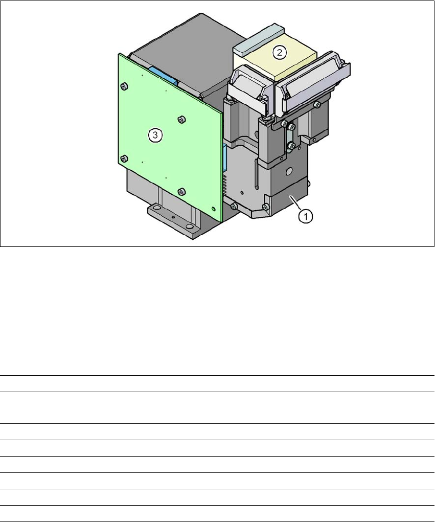
Fig. 6.15 - 1 C&P component camera, type 29, 27 x 27, digital
(1) Component camera lens and illumination
(2) Camera amplifier
(3) Illumination control
6.15.2 Technical data
6
Component dimensions 0.3 x 0.3 mm² to 18.7 x 18.7 mm²
Range of components 0201
a
to 18.7 x 18.7mm²
PLCC, SO, QFP, TSDP, SOT, MELF, CHIP, IC, BGA
Min. lead pitch 0.3 mm
Min. lead width 0.15 mm
Min. ball pitch 0.25 mm
Min. ball diameter 0.14 mm
Field of vision 31 x 31 mm²
Method of illumination Front-illumination (5 levels, programmable as required)
a) With 0201 package
6 Station extensions User Manual SIPLACE D3
6.16 0201 package From software version SR.605.xx 07/2008 EN Edition
334
6.16 0201 package
Item no. 00119720-xx 0201 package for C&P12, X/D series
We can supply the 0201 package for processing 0201 components with the 12-segment Col-
lect&Place head.
This contains:
– Component camera C&P (type 29), 27 x 27, digital, item no. 00119779
– Component sensor for the 12-segment C&P head, item no. 00118021
– 12 nozzles, type 706/906 Vectra ceramic, item no. 00345031
6.17 Coplanarity laser module
Item no. 00119719-xx Coplanarity module, X/D-series
6.17.1 Safety instructions for the sensor of the coplanarity module
The sensor works with a semiconductor laser of wave length 670 nm (visible/red).
The maximum optical output is ≤ 1 mW.
The sensor is classified as laser class 2.
– When operating the sensor, always follow the relevant regulations of VDE 0837 concerning
"Radiation safety for laser equipment" and German accident prevention regulation entitled
"Laser radiation" (BGV B2).
– Also follow the accident prevention regulations applicable in your country.
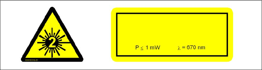
The following information plates are attached to the front and back of the sensor housing:
6
Fig. 6.17 - 1 Identification of laser class 2 for the sensor
LASER RADIATION
DO NOT LOOK INTO BEAM
LASER CLASS 2