00195760-0102_UM_D3_SR605_EN.pdf - 第340页
6 Station extensions User Manual SIPLACE D3 6.18 Vacuum pump From software version SR.605.xx 07/2008 EN Edition 340 6.18 V acuum pump Item no. 001 19794-xx V acuum pump, HF/X/D3, 220 V Item no. 001 19795-xx V acuum pump,…
User Manual SIPLACE D3 6 Station extensions
From software version SR.605.xx 07/2008 EN Edition 6.17 Coplanarity laser module
339
6
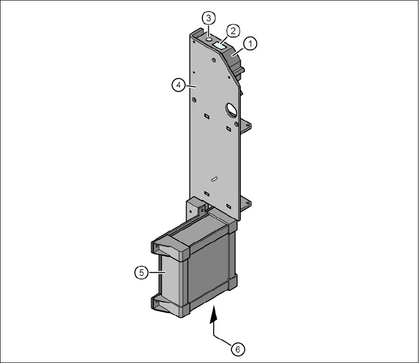
Fig. 6.17 - 4 Coplanarity laser module
(1) Laser sensor
(2) Detector
(3) Laser emitter
(4) Assembly bracket
(5) Controller
(6) LED displays and connections on the controller

6 Station extensions User Manual SIPLACE D3
6.18 Vacuum pump From software version SR.605.xx 07/2008 EN Edition
340
6.18 Vacuum pump
Item no. 00119794-xx Vacuum pump, HF/X/D3, 220 V
Item no. 00119795-xx Vacuum pump, HF/X/D3, 110 V
Item no. 00119792-xx Vacuum pump operation conversion kit
Every Collect&Place head has a separate vacuum generator that supplies the holding and place-
ment circuit with the vacuum that it needs. The vacuum generator works on the Venturi principle.
The compressed air consumption of the machine is, for example, around 550 Nl/min. This means
that the compressed air supply must be sized accordingly. If the owner does not have sufficient
capacity locally, the associated investment costs would be high, so we supply a vacuum pump that
will provide the necessary vacuum.
Other advantages of using the vacuum pump are:
– It roughly halves the machine's compressed air consumption.
– It reduces the input pressure.
– The machine can be easily integrated into existing lines.
– The ongoing operating costs reduce according to the energy costs.
The vacuum pump is maintenance-free and 100% oil-free. They have sufficient capacity to supply
the holding circuits of the Collect&Place heads.
PLEASE NOTE 6
There are currently vacuum pumps only for the 12-segment and 6-segment Collect & Place
heads.
Compressed air
consumption
without
vacuum pump
Compressed air
consumption
with
vacuum pump
a
Compressed air consumption with
4 tape cutters and in relation to the
placement head configuration
C&P / C&P / TH 550 Nl/min 300 Nl/min
a) Under normal atmospheric conditions at 20°C and 1013 hPa
User Manual SIPLACE D3 6 Station extensions
From software version SR.605.xx 07/2008 EN Edition 6.19 SIPLACE Productivity Lift
341
6.19 SIPLACE Productivity Lift
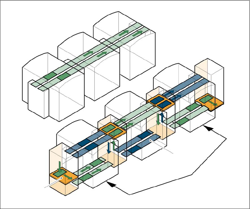
6.19.1 Concept of parallel placement
Placement lines are generally arranged in series and are linked to one another serially. The
placement program is processed sequentially while the PCBs are transported from one machine
to the next. This means that the placement of a PCB is distributed between various machines.
6
Fig. 6.19 - 1 A comparison of serial and parallel lines
When machines are connected in parallel, the components to be placed by individual machines
are combined. Several machines work through the same placement program. They place all the
components on one machine that would be distributed between several machines with serial pro-
cessing. When one machine runs out of capacity, the PCBs are moved to and placed at the next
machine with the same placement program. This combination of machines with the same compo-
nents to be placed is known as a group or “cluster”.
Serial line
Parallel line
Underfloor conveyor
Group (cluster)
Horizontal/
vertical lift