00195760-0102_UM_D3_SR605_EN.pdf - 第343页
User Manual SIPLACE D3 6 Station extensions From software version SR.605.xx 07/2008 EN Edition 6.19 SIPLACE Productivity Lift 343 6.19.3 Advant ages of the productivity lif t The productivity lift can raise the productiv…
6 Station extensions User Manual SIPLACE D3
6.19 SIPLACE Productivity Lift From software version SR.605.xx 07/2008 EN Edition
342
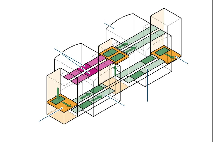
6.19.2 Implementing parallel placement
Lines with machines arranged in parallel take up a lot more space, so the parallel placement con-
cept was implemented with an underfloor conveyor and horizontal / vertical lift (HV shuttle). The
machines are still arranged in series, but the lift units and underfloor conveyors allow the line to
be operated in parallel. In this way, SIPLACE lines remain almost as compact as before.
Underfloor conveyor
Two conveyor belts carry empty or placed PCBs underneath the machines (see Fig. 6.19 - 1, page
341
). The maximum component height is 17 mm.
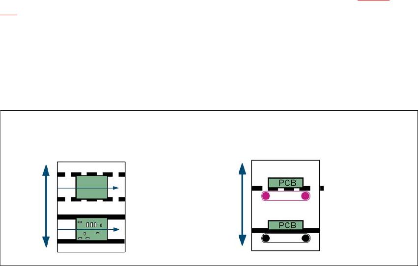
Horizontal/vertical lift (horizontal/vertical shuttle)
There is an HV shuttle at the start of a line, between the machines and at the end of the line. It
carries the PCBs between the underfloor and processing levels, and between the two tracks on
the underfloor conveyors.
6
Fig. 6.19 - 2 Horizontal / vertical shuttle (HV shuttle), conveyor track change and lift function
Horizontal conveyor
HV shuttle
Lift function
Vertical conveyor
Unplaced
Placed
Standard
conveyor level
Underfloor
conveyor level
HV shuttle
Conveyor track change
User Manual SIPLACE D3 6 Station extensions
From software version SR.605.xx 07/2008 EN Edition 6.19 SIPLACE Productivity Lift
343
6.19.3 Advantages of the productivity lift
The productivity lift can raise the productivity of a line overall because it increases the placement
rates of the machines on the line.
6
Fig. 6.19 - 3 Productivity lift, avoiding stoppages
6
If lines are connected in parallel, individual machines may fail without bringing the entire line to a
standstill. It is also possible access individual machines while the rest of the line continues placing
without interruption. This chaining increases the components to be placed per station and mini-
mizes conveyor idle times. This leads to an overall higher placement rate on the line.
This could be for
– process-related investigations or test operation
– programming PCB fiducials, package forms or test placements
– maintenance or repairs
– operating errors, such as not splicing tapes on in good time or missing components.
Another advantage is that the line can be reconfigured as required using the software, without
having to reset the machines.
Conveyor section, processing
Placement machine
Horizontal
and vertical lift
Underfloor con-
veyor
Track change
6 Station extensions User Manual SIPLACE D3
6.20 Vision Teach Station From software version SR.605.xx 07/2008 EN Edition
344
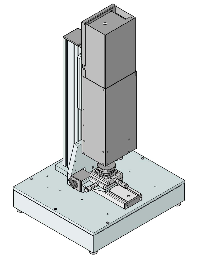
6.20 Vision Teach Station
Item no. 00119788-xx Vision teach station
6
Fig. 6.20 - 1 Vision teach station with component camera, type 33