00195760-0102_UM_D3_SR605_EN.pdf - 第61页
User Manual SIPLACE D3 2 Operational safety From software version SR.605.xx 07/2008 EN Edition 2.5 Safety instructions for operating the machine 61 → Always hold the grab handles when opening or closing the protective co…
2 Operational safety User Manual SIPLACE D3
2.5 Safety instructions for operating the machine From software version SR.605.xx 07/2008 EN Edition
60
2.5 Safety instructions for operating the machine
2.5.1 Safety instructions for closing the protective covers
To prevent any risk of injury when the protective covers on machines are closed, the owner must
instruct his operators to use the protective covers exactly as specified in the following instructions.
CAUTION
RISK OF CRUSHING HANDS
IF THE PROTECTIVE COVERS ARE NOT CLOSED CORRECTLY 2
2
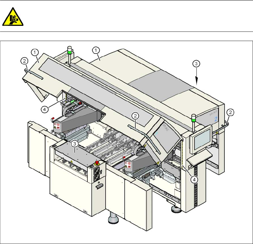
Fig. 2.5 - 1 Safety instructions for closing the protective covers
(1) Protective covers
(2) Grab handles
(3) Cover flaps over the PCB conveyor
(4) Warning strips

User Manual SIPLACE D3 2 Operational safety
From software version SR.605.xx 07/2008 EN Edition 2.5 Safety instructions for operating the machine
61
→ Always hold the grab handles when opening or closing the protective covers.
→ When closing, do not reach into the gap between the protective cover and the machine panel.
The area is identified by a yellow-black warning strip (item 4 in Fig. 2.5 - 1
, page 60).
→ When you close the covers, make sure that there is no-one else in the cover swiveling range.
→ When you close the covers, make sure that there is no-one else in the vicinity of the opposite
component trolley location.
2.5.2 Safety instructions for processing capacitors based on powdered metal
There is a risk associated with processing capacitors based on powdered metal (e.g. tantalum).
The risk is that
– an exothermic reaction, i.e. a sudden build-up of heat, may occur, if these components are
damaged. If the ambient conditions are unfavorable, and depending on the capacitance, this
buildup of heat can cause damage.
– this effect can occur when these components are cut.
Please contact your suppliers to clarify whether the components that you handle are affected.
In extremely rare cases, this risk can occur in the tape cutter of SIPLACE machines, with the re-
mote possibility of causing a smoldering fire in the waste tape.
The ambient conditions are unfavorable if:
(1) The components remain on the tape while the set tape cycle is checked (since the operator
can cycle the feeder module onward without removing components during this check).
(2) The components remain on the tape, e.g. due to a tear in the cover foil.
(3) The components remain on the tape, and the components or tape do not conform to the spec-
ification, thus increasing the pickup error rate.
Please follow the instructions given below to minimize the risk when placing capacitors based on
powdered metal.
(1) If the component tape is cycled onward manually, the operator must remove any components
remaining in the tape pocket.
(2) If the cover foil tears, the operator must remove any components remaining on the tape.
To ensure that tantalum capacitors do not cause the tape material to burn when it is cut as a result
of pick-up errors, the user interface has been extended to include the "Remove component from
tape in the event of a pick-up error" option. This option must be enabled in SIPLACE Pro. On the
placement machine, the component that was not picked up is paced forward again until it is ready
for removal from the component tape. The track is deactivated and the operator is sent an error
message to remind him to pick up the tantalum component from the tape.
PLEASE NOTE 2
The manual extraction by the operator of tantalum capacitors that have not been picked up is
described in Section 3.9.6 on page 141.
2 Operational safety User Manual SIPLACE D3
2.5 Safety instructions for operating the machine From software version SR.605.xx 07/2008 EN Edition
62
2.5.3 Safety instructions for removing nozzles from Collect&Place heads
CAUTION
RISK OF INJURY TO FINGERS BY SHARP NOZZLES 2
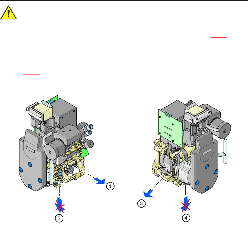
Do not remove the nozzles in the pick-up/placement position (item 2 and 4 in Fig. 2.5 - 2).
The procedure for removing nozzles manually from the sleeve is as follows:
→ Pace the sleeve from which the nozzle is to be removed to the removal point (item 1 and 3 in
Fig. 2.5 - 2
).
→ Remove the nozzle from the sleeve here.
2
Fig. 2.5 - 2 Position of the sleeve during a manual nozzle change
(1) Removal position for sleeves and nozzles, C&P12
(2) Pick-up and placement position, C&P12
(3) Removal position for sleeves and nozzles, C&P6
(4) Pick-up and placement position, C&P6