00195760-0102_UM_D3_SR605_EN.pdf - 第68页
2 Operational safety User Manual SIPLACE D3 2.6 Safety equipment From software version SR.605.xx 07/2008 EN Edition 68 two cover flaps (item 3 and 4 ) over the input or output belt of the PCB conve yor prevent acc ess to…
User Manual SIPLACE D3 2 Operational safety
From software version SR.605.xx 07/2008 EN Edition 2.6 Safety equipment
67
2.6 Safety equipment
2.6.1 Protective covers
2
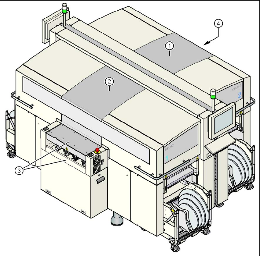
Fig. 2.6 - 1 Protective covers
(1) Protective cover, short
(2) Protective cover, long
(3) Cover flap and hand guard on the input belt
(4) Cover flap and hand guard on the output belt
2
The traveling range of the gantries has two protective covers that can be swung upwards (items
1 and 2). There are side screens to prevent access to the inside of the machine from the side. The
2 Operational safety User Manual SIPLACE D3
2.6 Safety equipment From software version SR.605.xx 07/2008 EN Edition
68
two cover flaps (item 3 and 4) over the input or output belt of the PCB conveyor prevent access
to the PCB conveyor.
Function 2
The main power supply to the gantry axes is interrupted immediately if one of the protective covers
is swiveled up or one of the cover flaps on the PCB conveyor is raised. The gantry axes stop mov-
ing. The message "Close cover" is displayed on the screen.
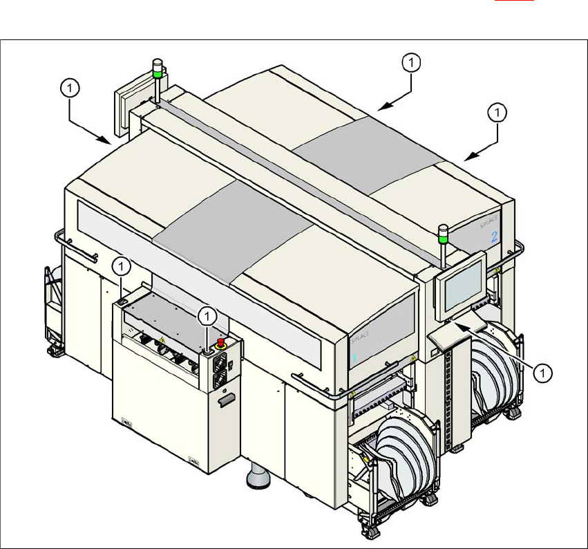
→ Close the protective covers and press one of the start buttons (item 1 in Fig. 2.6 - 2
) to con-
tinue placement.
2
Fig. 2.6 - 2 Position of the start buttons (white) on the machine
(1) Start button (white) on the machine
User Manual SIPLACE D3 2 Operational safety
From software version SR.605.xx 07/2008 EN Edition 2.6 Safety equipment
69
2.6.2 Switches and buttons on the machine
2.6.2.1 Position of switches and buttons on the machine
2
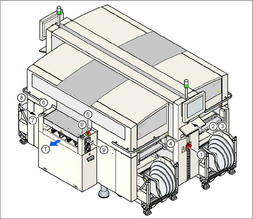
Fig. 2.6 - 3 Position of switches and buttons - View of the PCB output side
(1) Main power switch
(2) Stop button (black) on the operator panel on the power supply side
(3) Start button (white) on the operator panel on the power supply side
(4) Component counter on the operator panel on the power supply side
(5) EMERGENCY STOP button on the output side
(6) Start button (white) on the output side
(7) Stop button (black) on the output side
(8) Button (black) for docking the component trolley in or out, location 2
(9) Button (black) for docking the component trolley in or out, location 3
(T) PCB transport direction