00195760-0102_UM_D3_SR605_EN.pdf - 第74页
2 Operational safety User Manual SIPLACE D3 2.6 Safety equipment From software version SR.605.xx 07/2008 EN Edition 74 2.6.3 Position of protective cont act or combination a nd service socket 2 Fig. 2.6 - 6 Position of p…

User Manual SIPLACE D3 2 Operational safety
From software version SR.605.xx 07/2008 EN Edition 2.6 Safety equipment
73
EMERGENCY STOP button with positive latching
(item 5 in Fig. 2.6 - 3
and item 1 in Fig. 2.6 - 4) 2
The EMERGENCY STOP button is red and latches in the ON position when pressed. When you
press the EMERGENCY STOP button the switching contact of the EMERGENCY STOP circuit
opens and the protective contactor combination (PCC K6) trips. The link voltage (250 VDC) for the
gantry axes and the link voltage (145 VDC) for the star axes is switched off. The servo amplifiers
for the DP and Z axes are still supplied with 40 VDC. The signaling contact of the EMERGENCY
STOP button opens and the message "EMERGENCY STOP pressed" appears on the screen.
The following modules are deactivated:
– PCB conveyor
– PCB clamping
– Width adjustment
– PCB stopper
– Used tape cutter.
PLEASE NOTE
Placement is interrupted and can then either be continued or canceled once the machine is work-
ing correctly again. 2
Button for docking the component trolley in or out 2
There are two buttons on the input and output sides of the machine for docking the component
trolley in or out.
– Button (item 6 in Fig. 2.6 - 4
) for docking the component trolley in or out at location 1
– Button (item 8 in Fig. 2.6 - 3
) for docking the component trolley in or out at location 2
– Button (item 9 in Fig. 2.6 - 3
) for docking the component trolley in or out at location 3
– Button (item 7 in Fig. 2.6 - 4
) for docking the component trolley in or out at location 4
The component trolleys can only be docked in if the protective covers are closed.
Protective cover switches 1, 2, 3 and 4 (item 1, 2, 3 and 4 in Fig. 2.6 - 5) and protective switch
for the cover flaps on the PCB conveyor input and output side (items 5 and 6 in Fig. 2.6 - 5
)2
These switches check whether the protective covers and the cover flaps are closed. When they
are closed, the EMERGENCY STOP contact and the signaling contact are closed. If one of the
covers or the cover flaps is opened, the EMERGENCY STOP contact and the signaling contact
open. Some components are deactivated or remain active (see Fig. 2.6 - 8
, page 78).
2 Operational safety User Manual SIPLACE D3
2.6 Safety equipment From software version SR.605.xx 07/2008 EN Edition
74
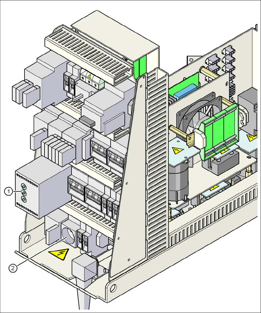
2.6.3 Position of protective contactor combination and service socket
2
Fig. 2.6 - 6 Position of protective contactor combination and service socket
2
(1) Protective contactor combination
(2) Service socket
User Manual SIPLACE D3 2 Operational safety
From software version SR.605.xx 07/2008 EN Edition 2.6 Safety equipment
75
Protective contactor combination 3TK2806 (item 1 in Fig. 2.6 - 6) 2
The protective contactor combination is contained in the power supply unit. It is used to monitor
the EMERGENCY STOP circuits and safety equipment.
There are three conditions that must be fulfilled in order to activate the protective contactor com-
bination:
– The "software enable" signal must have been sent.
– The EMERGENCY STOP loop must be closed.
– The start button must have been pressed.
On the front panel of the protective contactor combination, there are three green operating display
LEDs (see Fig. 2.6 - 7
, page 76):
– The "Mains" LED indicates that voltage is present.
– The "Channel 1" and "Channel 2" LEDs light up if the start button was pressed, the EMER-
GENCY STOP loop is closed and the signaling circuit is not signaling a fault status.
Service socket (item 2 in Fig. 2.6 - 6) 2
The service socket is contained in the power supply unit and is protected by the cover. It can only
be used if the machine is connected to the main power supply via a 5-wire connection (L1, L2, L3,
N, and PE). If a 4-wire connection is used, e.g. without N, the socket cannot be used.
WARNING 2
Always follow the safety instructions concerning potentially lethal voltages - even when the
machine is switched off. (See Section 2.1.3 from page 34 onwards.)