00195760-0102_UM_D3_SR605_EN.pdf - 第79页
User Manual SIPLACE D3 2 Operational safety From software version SR.605.xx 07/2008 EN Edition 2.6 Safety equipment 79 2.6.5 Hand guard at the co mponent trolley locations W ARNING 2 All locations must be equipped wit h …
2 Operational safety User Manual SIPLACE D3
2.6 Safety equipment From software version SR.605.xx 07/2008 EN Edition
78
2
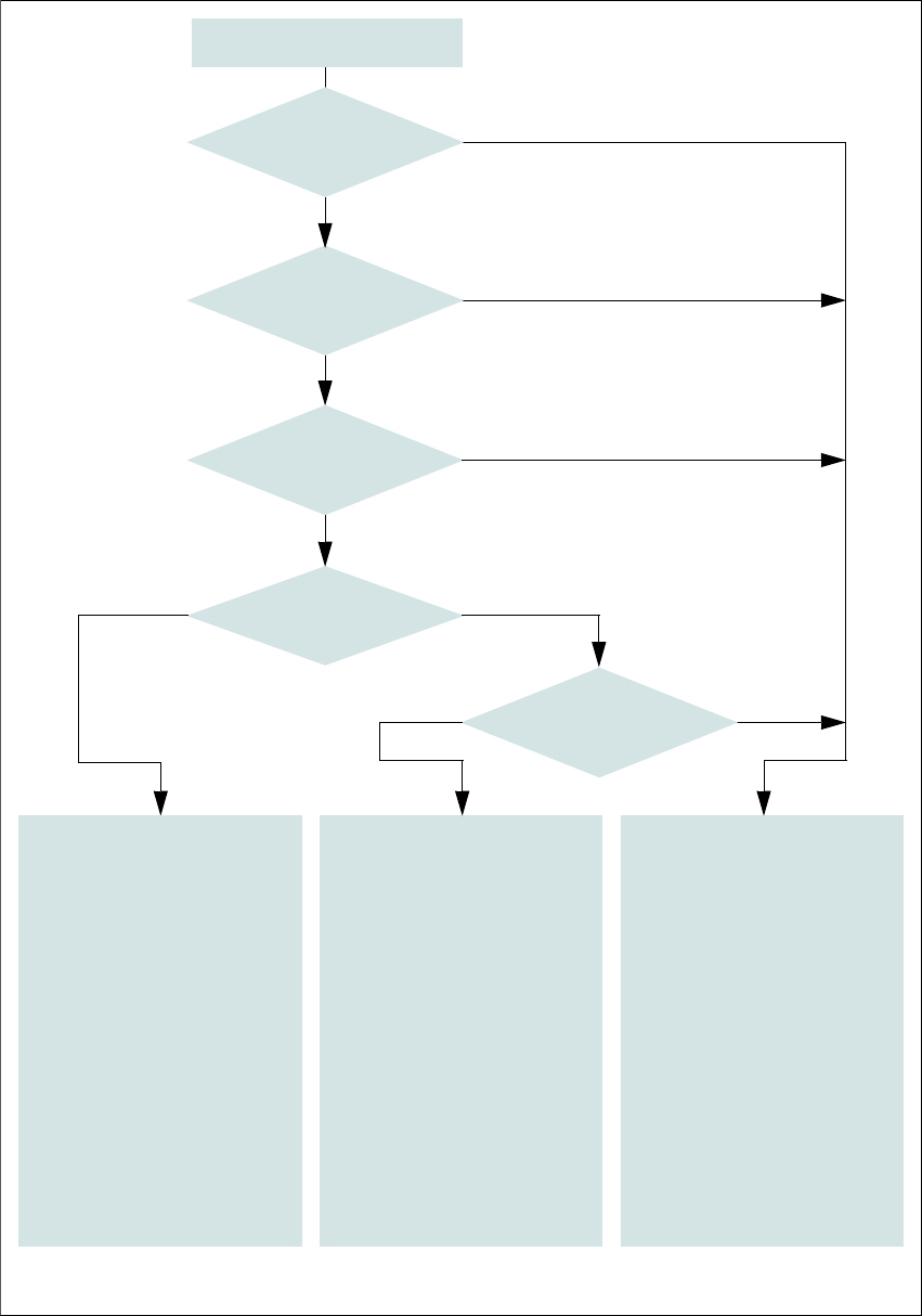
Fig. 2.6 - 8 EMERGENCY STOP loops
Start button pressed
No
No
Yes
No
No
Yes
Yes
No
Yes
2
Active
PCC*) No
Voltage
Y axis 0 V
X axis 0 V
Star axis 0 V
DP axis 40 VDC
Z axis 40 VDC
Active
PCB conveyor Yes
Lifting table No
PCB clamp No
Width adjustment No
Laser light barrier No
Used tape cutter No
CO trolley docking unit Yes
2
Active
PCC*) No
Voltage
Y axis 0 V
X axis 0 V
Star axis 0 V
DP axis 40 VDC
Z axis 40 VDC
Active
PCB conveyor No
Lifting table No
PCB clamp No
Width adjustment No
Laser light barrier No
Used tape cutter No
CO trolley docking unit Yes
*) PCC protective contactor combination K6
Yes
Compressed
air min. 0.5 MPa
(5.0 bar)?
EMERGENCY STOP button
pressed?
Protective cover open?
Component trolley
EMERGENCY STOP circuit
interrupted?
Barrier
activated on the user
interface?
2
Active
PCC*) Yes
Voltage
Y axis 250 VDC
X axis 250 VDC
Star axis 145 VDC
DP axis 40 VDC
Z axis 40 VDC
Active
PCB conveyor Yes
Lifting table Yes
PCB clamping Yes
Width adjustment Yes
Laser light barrier Yes
Used tape cutter Yes
CO trolley docking unit Yes
User Manual SIPLACE D3 2 Operational safety
From software version SR.605.xx 07/2008 EN Edition 2.6 Safety equipment
79
2.6.5 Hand guard at the component trolley locations
WARNING 2
All locations must be equipped with feeder modules in order to guarantee operational reliability. If
there are not enough feeder modules available, unassigned locations should be fitted with a
hand guard (dummy feeder module). When a waffle-pack holder is set up, the remaining loca-
tions have to be protected again with a hand guard.
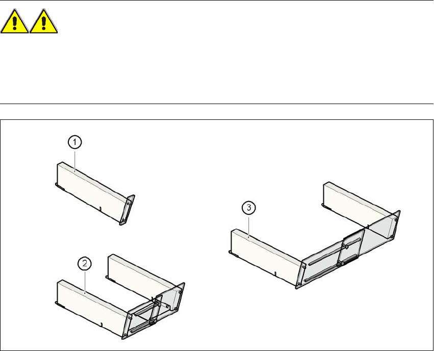
Fig. 2.6 - 9 Hand guard for component trolleys
2
(1) Hand guard for 1 location item no. 00116961-01
(2) Hand guard for 6 to 10 locations item no. 00116962-01
(3) Hand guard for 11 to 20 locations item no. 00116963-01
2 Operational safety User Manual SIPLACE D3
2.7 Residual voltages and discharge times in the machine From software version SR.605.xx 07/2008 EN Edition
80
2.7 Residual voltages and discharge times in the
machine
If the EMERGENCY STOP button is pressed or the placement system is switched off, the 250
VDC link voltage for the gantry axes and the 145 VDC link voltage for the star axes are reduced
to harmless residual voltages in a very short time.
WARNING 2
The machine is supplied with 3 x 200 VAC, 3 x 208 VAC, 3 x 230 VAC, 3 x 380 VAC,
3x400VAC or 3x415VAC ± 5%, 50/60Hz mains voltage. This means that some parts of the
system carry potentially lethal voltages - even when switched off at the main power switch. Incor-
rect handling of the machine can therefore result in death or severe injury or considerable dam-
age to equipment.
→ Always follow the applicable accident prevention and DIN regulations (particularly DIN EN 60
204, part 1).
→ The guards over the power supply unit and the axis unit must ONLY be opened by appropri-
ately qualified and trained personnel.
2
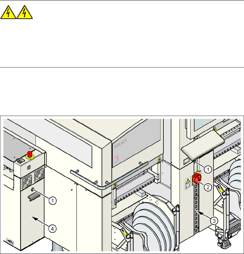
Fig. 2.7 - 1 Power supply unit
(1) Padlock with bolt in the cover
(2) Main power switch
(3) Power supply unit behind the cover
(4) Axis unit