00195760-0102_UM_D3_SR605_EN.pdf - 第84页
2 Operational safety User Manual SIPLACE D3 2.9 Energy state of the machine after switching off at the main po wer switch From software version SR.605.xx 07/2008 EN Edition 84 2.9 Energy st ate of the machine af ter swit…
User Manual SIPLACE D3 2 Operational safety
From software version SR.605.xx 07/2008 EN Edition 2.8 Disabling the compressed air supply and discharging the pressure
83
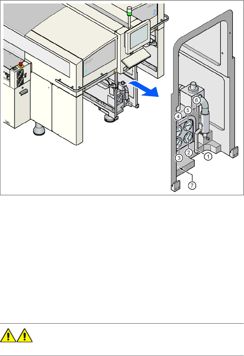
Fig. 2.8 - 1 Compressed air unit on the machine
(1) Stop valve
(2) Manometer for the machine component supply pressure
Desired pressure: 0.48 ± 0.025 MPa, 4.8 ± 0.25 bar (display range 0 - 0.6 MPa, 0 - 6 bar)
(3) Manometer for the gantry distributor supply pressure
Desired pressure: 0.46 ± 0.01 MPa, 4.6 ± 0.1 bar (display range 0 - 0.6 MPa, 0 - 6 bar)
(4) Manometer for the bulk case feeder modules supply pressure
Desired pressure: 0.25 ± 0.05 MPa, 2.5 ± 0.5 bar (display range 0 - 0.6 MPa, 0 - 6 bar)
(5) Manometer for the input pressure
Desired pressure: 0.5 - 1.0 MPa, 5 - 10 bar (display range: 0 - 1.0 MPa, 0 - 10 bar)
(6) Compressed air filter
(7) Hexagon socket head screw for fixing the pneumatic unit
WARNING
NEVER detach compressed air lines while they are still pressurized. Risk of injury. 2
2 Operational safety User Manual SIPLACE D3
2.9 Energy state of the machine after switching off at the main power switch From software version SR.605.xx 07/2008 EN Edition
84
2.9 Energy state of the machine after switching off at
the main power switch
2
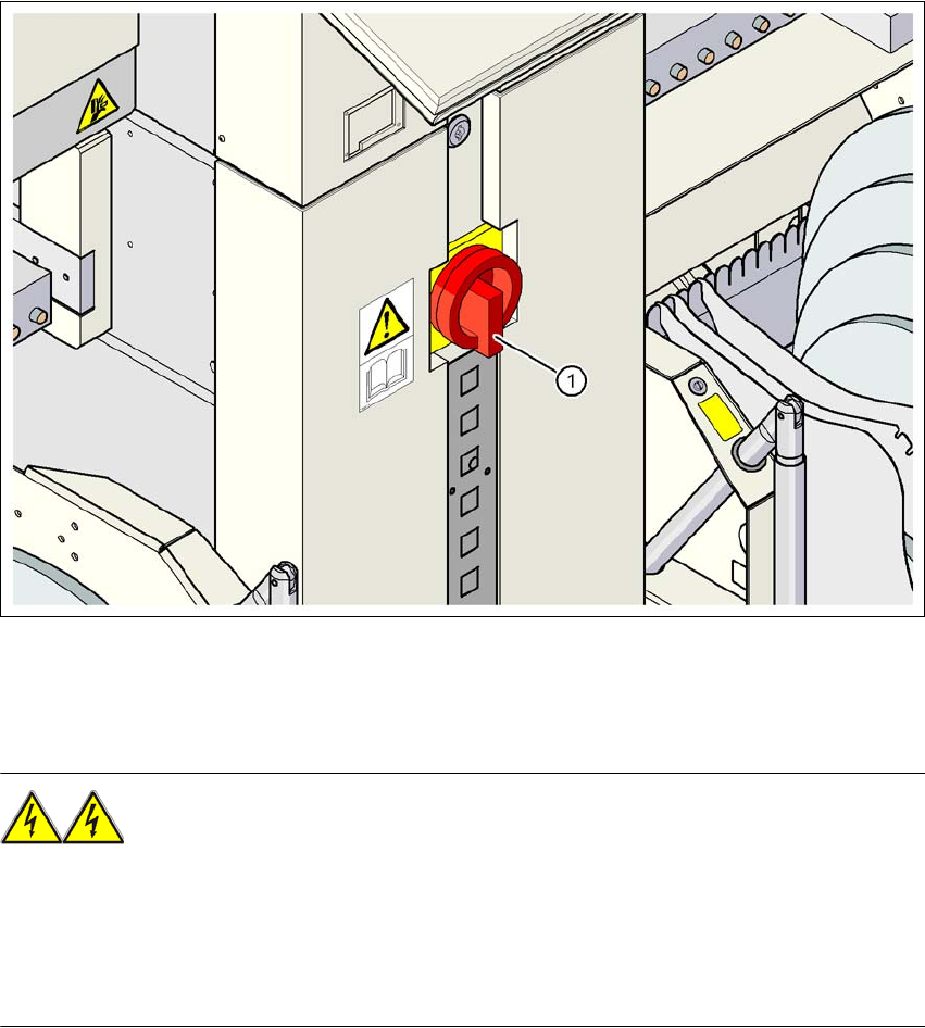
Fig. 2.9 - 1 Position of the power supply on the machine
2
WARNING
The machine is supplied with 3 x 200 VAC, 3 x 208 VAC, 3 x 230 VAC, 3 x 380 VAC, 3 x 400 VAC
or 3 x 415 VAC ± 5 %, 50/60 Hz mains voltage. This means that some parts of the system carry
potentially lethal voltages - even when switched off at the main power switch. Incorrect handling
of the machine can therefore result in death or severe injury or considerable damage to equip-
ment. 2
→ Always follow the applicable accident prevention and DIN regulations (particularly DIN EN 60
204, part 1).
→ The guard over the power supply unit must ONLY be opened by appropriately qualified and
trained personnel.
(1) Main power switch

User Manual SIPLACE D3 2 Operational safety
From software version SR.605.xx 07/2008 EN Edition 2.9 Energy state of the machine after switching off at the main power switch
85
2.9.1 Placement system switched off at the main switch, but still connected
WARNING
The following components still carry potentially lethal voltages even if the main power switch is
switched off:
– Cable connection terminals L1, L2 and L3 in the main power switch Q1 (see Fig. 2.9 - 3
,
page 87
)
– Service socket X102 (see Fig. 2.9 - 3
, page 87)
– Automatic circuit breaker F1 for the service socket (see Fig. 2.9 - 3
, page 87)
– Z1 line filter (see Fig. 2.9 - 4
, page 88)
– L20 discharge reactor with fuses F21, F22, and F23 (see Fig. 2.9 - 4
, page 88)
– Terminal block X100 for connecting the power supply cable (see Fig. 2.9 - 4
, page 88)
– The color of all individual wires, which still carry potentially lethal voltages even if the main
power switch is switched off, is brown.
– Axis unit