00195760-0102_UM_D3_SR605_EN.pdf - 第86页
2 Operational safety User Manual SIPLACE D3 2.9 Energy state of the machine after switching off at the main po wer switch From software version SR.605.xx 07/2008 EN Edition 86 2 Fig. 2.9 - 2 Position of the co mputer uni…

User Manual SIPLACE D3 2 Operational safety
From software version SR.605.xx 07/2008 EN Edition 2.9 Energy state of the machine after switching off at the main power switch
85
2.9.1 Placement system switched off at the main switch, but still connected
WARNING
The following components still carry potentially lethal voltages even if the main power switch is
switched off:
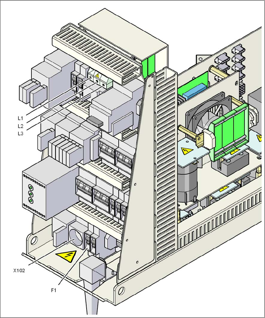
– Cable connection terminals L1, L2 and L3 in the main power switch Q1 (see Fig. 2.9 - 3
,
page 87
)
– Service socket X102 (see Fig. 2.9 - 3
, page 87)
– Automatic circuit breaker F1 for the service socket (see Fig. 2.9 - 3
, page 87)
– Z1 line filter (see Fig. 2.9 - 4
, page 88)
– L20 discharge reactor with fuses F21, F22, and F23 (see Fig. 2.9 - 4
, page 88)
– Terminal block X100 for connecting the power supply cable (see Fig. 2.9 - 4
, page 88)
– The color of all individual wires, which still carry potentially lethal voltages even if the main
power switch is switched off, is brown.
– Axis unit
2 Operational safety User Manual SIPLACE D3
2.9 Energy state of the machine after switching off at the main power switch From software version SR.605.xx 07/2008 EN Edition
86
2
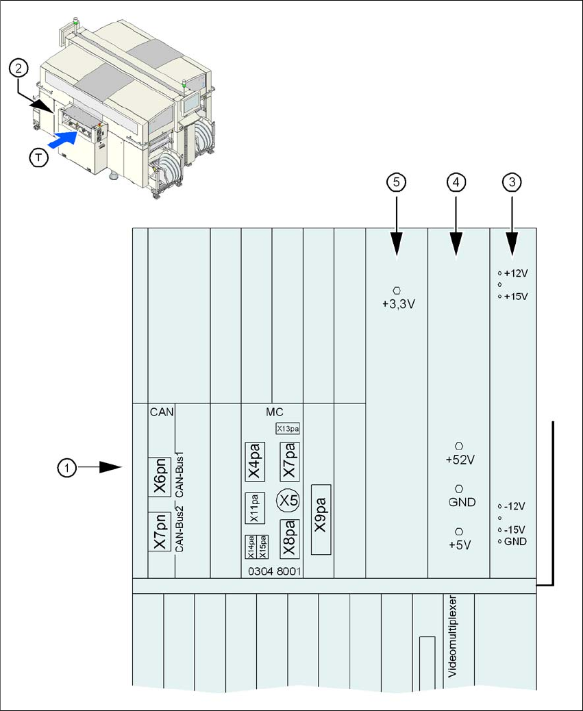
Fig. 2.9 - 2 Position of the computer unit
(1) Computer unit (top part)
(2) Power supply unit ± 12 VDC/± 15 VDC
(3) Power supply unit + 5 VDC/+ 52 VDC
(4) Power supply unit + 3.3 VDC
(T) Direction of PCB transport
User Manual SIPLACE D3 2 Operational safety
From software version SR.605.xx 07/2008 EN Edition 2.9 Energy state of the machine after switching off at the main power switch
87
2
Fig. 2.9 - 3 Power supply unit, front view
Q1 Main power switch
X102 Service socket
F1 Fuse for the service socket