00195760-0102_UM_D3_SR605_EN.pdf - 第87页
User Manual SIPLACE D3 2 Operational safety From software version SR.605.xx 07/2008 EN Edition 2.9 Energy stat e of the machine after switching off at the main power switch 87 2 Fig. 2.9 - 3 Power supply unit, front view…
2 Operational safety User Manual SIPLACE D3
2.9 Energy state of the machine after switching off at the main power switch From software version SR.605.xx 07/2008 EN Edition
86
2
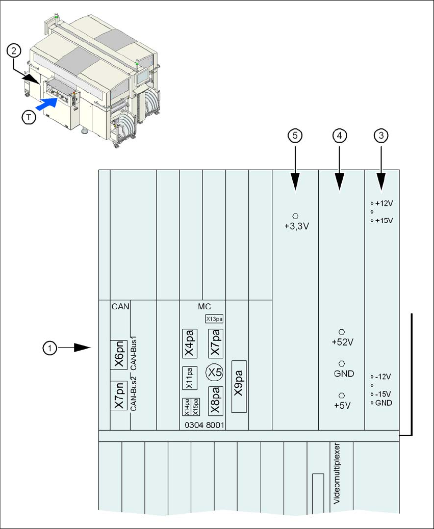
Fig. 2.9 - 2 Position of the computer unit
(1) Computer unit (top part)
(2) Power supply unit ± 12 VDC/± 15 VDC
(3) Power supply unit + 5 VDC/+ 52 VDC
(4) Power supply unit + 3.3 VDC
(T) Direction of PCB transport
User Manual SIPLACE D3 2 Operational safety
From software version SR.605.xx 07/2008 EN Edition 2.9 Energy state of the machine after switching off at the main power switch
87
2
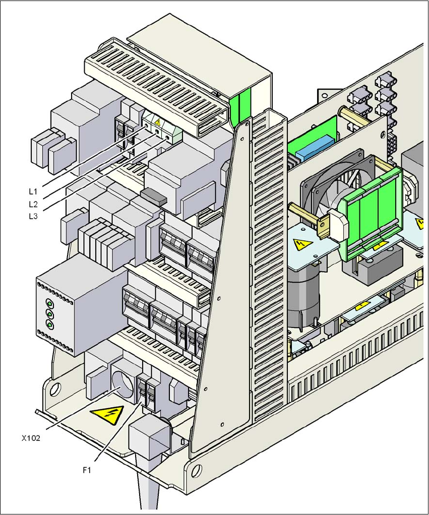
Fig. 2.9 - 3 Power supply unit, front view
Q1 Main power switch
X102 Service socket
F1 Fuse for the service socket
2 Operational safety User Manual SIPLACE D3
2.9 Energy state of the machine after switching off at the main power switch From software version SR.605.xx 07/2008 EN Edition
88
2
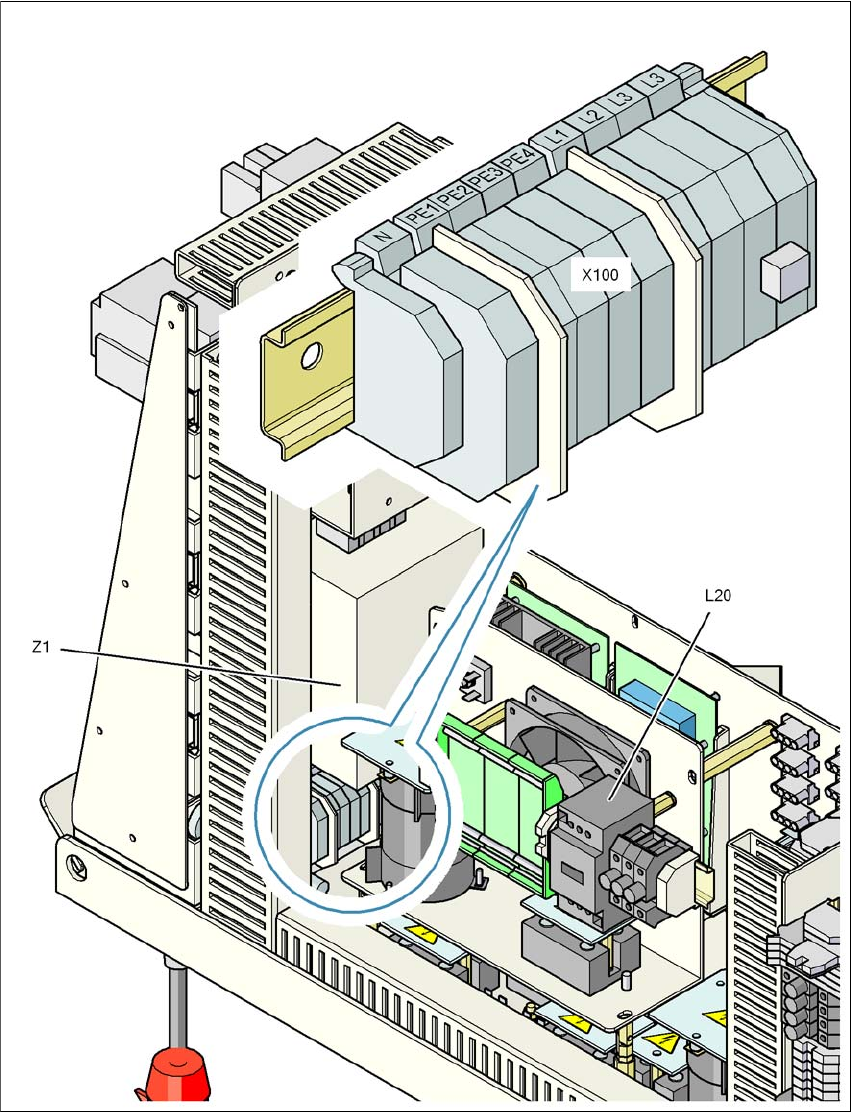
Fig. 2.9 - 4 Power supply unit, back view
X100 Cable connection terminal for the power supply cable
L20 Discharge reactor with fuses F21, F22 and F23
Z1 Line filter