Productivity Lift.pdf - 第26页
2 Operating safety User Manual - Productivity Lift 2.2 Warning signals and warning and danger symbol s on the Productivity Lift Edition 02/2004 18 The transport locks (U-bars and clamping piece) ar e necessary safety pre…
User Manual - Productivity Lift 2 Operating safety
Edition 02/2004 2.2 Warning signals and warning and danger symbols on the Productivity Lift
17
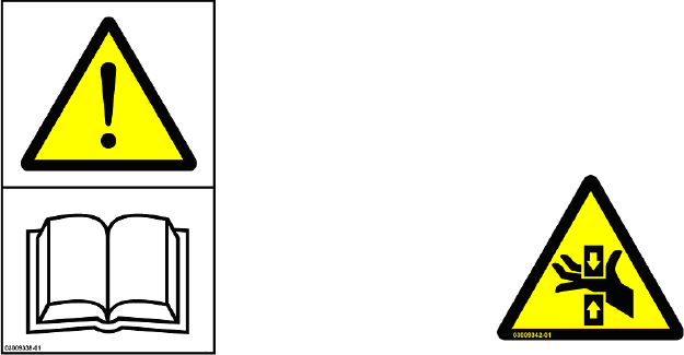
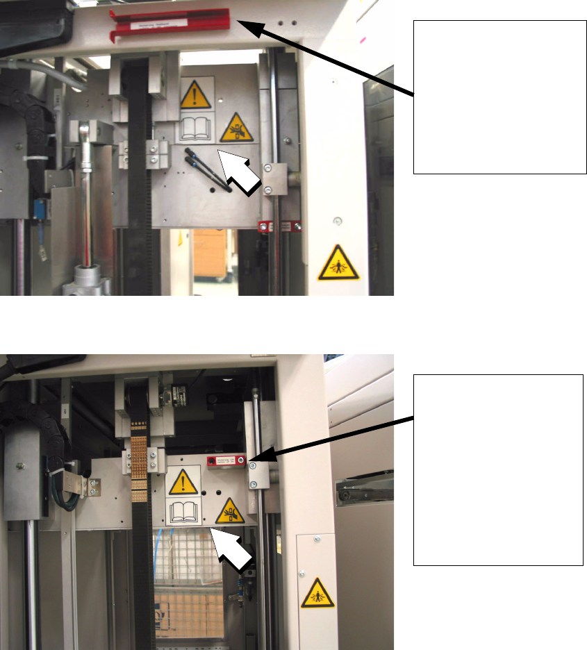
2.2.3.2 Warning sticker W 201 in combination with W 203
Sticker position: Visible after opening of the service door on the front side of the shuttle
transport.
Amount per machine: Sticker combination 1
Category: WARNING
Fig. 2 - 3 Warning sticker W201 in combination with W 203
SAFE OPERATION OF THE MACHINE
Knowledge of and compliance with the user manual and the safety instructions is a requirement
for the safe operation of the machine and safe intervention into the lift area.
A PCB may ONLY be removed in normal mode and THEN only out of the lift interior and only if
the operator can reach the PCB without putting his arm in above the lower arm or bending his up-
per body. The operator may not reach from the lift interior through to the SPLC, even if he/she
wishes to free a jammed PCB from the SPLC.
The service engineer or a suitably qualified person must be commissioned for all intervention in
the machine which exceeds the scope of the normal mode as described here. BEFORE he/she
begins the work, the service engineer or the suitably qualified person must fit the transport locks
according to the instructions in this user manual (see section 2.5 “Fitting the transport locks”), to
secure the height position of the shuttle transport and also of the top conveyor.
Non-compliance with these instructions can lead to severe injury to death!
A
rt.-No. 03009338-01 Art.-No. 03009342-01
in combination with
2 Operating safety User Manual - Productivity Lift
2.2 Warning signals and warning and danger symbols on the Productivity Lift Edition 02/2004
18
The transport locks (U-bars and clamping piece) are necessary safety precautions! The transport
locks must be removed before the lift axle is reactivated and then stored in the lift unit in the des-
ignated position, so that they are always available.
Fig. 2 - 4 Service door: Warning sticker underneath the main switch
Fig. 2 - 5 Service door: Warning sticker underneath the main switch
Transport locks:
U-bars to secure the shut-
tle unit (Fitted onto the pis-
ton rod)
Transport locks:
Clamping piece for secur-
ing the „Top conveyor“
(Fitted against the under-
side of the „Top con-
veyor“).
User Manual - Productivity Lift 2 Operating safety
Edition 02/2004 2.2 Warning signals and warning and danger symbols on the Productivity Lift
19
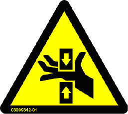
2.2.3.3 Warning sticker W 203
Article -No.: 03009342-01
Sticker positions:on the lift unit, visible after the operator doors have been opened:
– 1 x on the lower lift frame
– 1x on the lift floor near to the operator door.
– 4x on the lift interior, above the left and right transfer openings, top
and bottom
– 4x on the lift exterior, above the left and right transfer openings, top
and bottom
– 1x on the base plate of the shuttle transport near to the operator side
– 1x on the front side of the „top conveyor“
– 2x on the front side of the shuttle conveyor (left and right)
Sticker positions: on the lift unit, visible after opening the service door
– 1x on the „top conveyor“ (in combination with the warning sticker W
201) or in special cases
– 1 x on the shuttle conveyor (in combination with the warning sticker
W 201)
Sticker positions:on the lift unit, visible after opening the upper lift cover:
– 2 x on the base plate of the „top conveyor“, in the area of the mini-
mum transport width.
Amount per machine: 17
Category: WARNING
Fig. 2 - 6 Warning sticker W203, Art-No. 03009342-01
DANGER OF CRUSHING!
Intervention can lead to injuries on the arms and the hands.
Do not intervene with a running machine!
In this context, the following detailed safety texts are neces-
sary in connection with danger of crushing: