Productivity Lift.pdf - 第32页
2 Operating safety User Manual - Productivity Lift 2.2 Warning signals and warning and danger symbol s on the Productivity Lift Edition 02/2004 24 Fig. 2 - 12 Warning sticker W203 on the facing side the top conveyor Fig.…
User Manual - Productivity Lift 2 Operating safety
Edition 02/2004 2.2 Warning signals and warning and danger symbols on the Productivity Lift
23
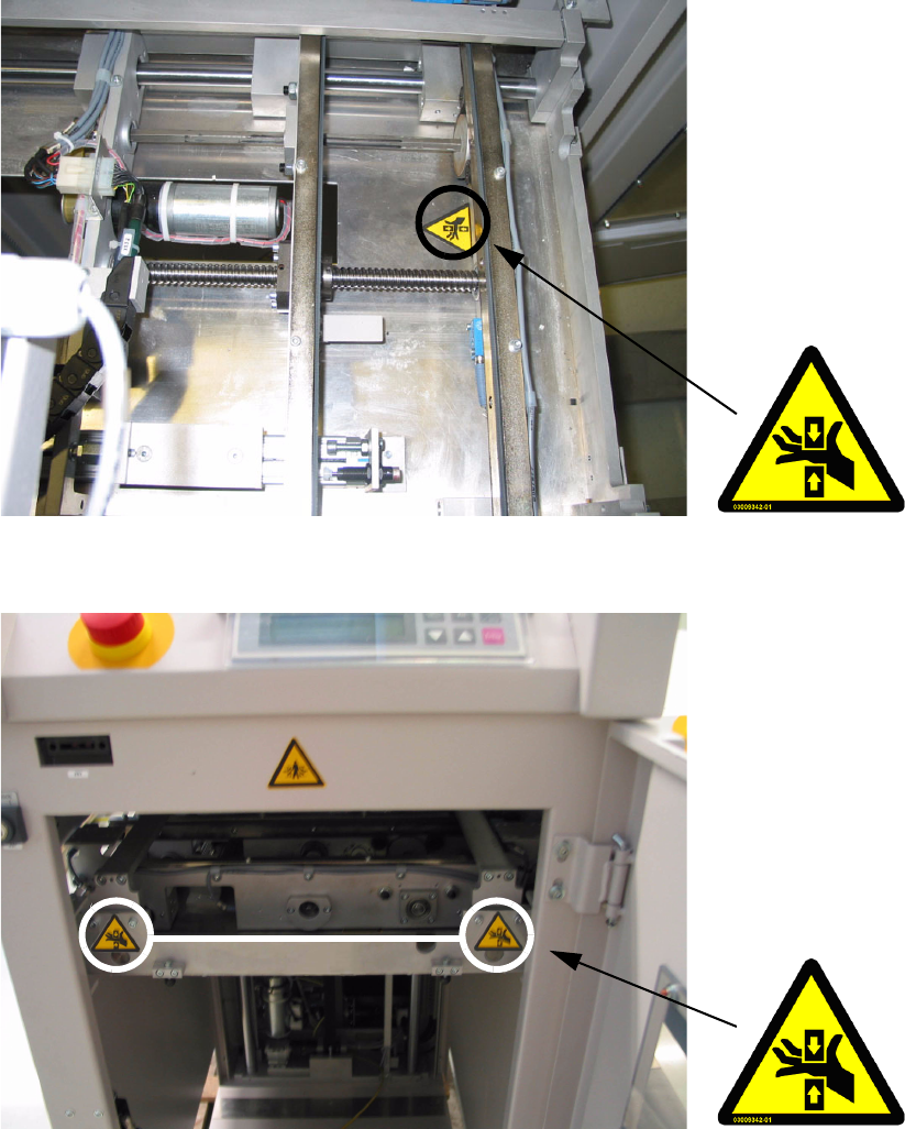
Fig. 2 - 10 Warning sticker W203 on the base plate of the Shuttle conveyor
Fig. 2 - 11 Warning sticker W203 on the front side of the shuttle conveyor
2 Operating safety User Manual - Productivity Lift
2.2 Warning signals and warning and danger symbols on the Productivity Lift Edition 02/2004
24
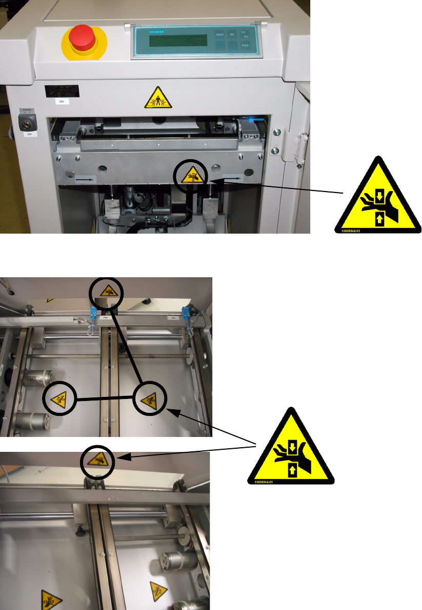
Fig. 2 - 12 Warning sticker W203 on the facing side the top conveyor
Fig. 2 - 13 Warning symbol W203 on the base plate of the top conveyor
Warning symbol on the base
plate of the double-track con-
veyor (top conveyor) and on
the right transfer opening.
Warning sticker on the right
transfer opening,
User Manual - Productivity Lift 2 Operating safety
Edition 02/2004 2.2 Warning signals and warning and danger symbols on the Productivity Lift
25
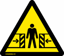
2.2.3.4 Danger sticker W 217
Article-No.: 03025062-01
Sticker position: on the lift unit, visible after opening the operator doors.
3 x on the lift frame, top + left+ bottom.
Sticker positions: visible after opening the service doors.
1x on the right side of the lift frame
Amount per machine: 4
Category: DANGER
Fig. 2 - 14 Warning sticker W217, Art-No. 03025062-01
DANGER OF CRUSHING up to DANGER OF LIFE!
It is strictly forbidden for a person to fully bend into the lift area!.
When the lift’s Z-axle is not secured, then the only permissible action is the removal of a PCB in
normal mode and THEN only out of the lift interior and only if the operator can reach the PCB with-
out putting his arm into the lift interior above the lower arm. The operator may not reach from the
lift interior through to the SPLC.
Before all consequential intervention, which involves in any way, the entry of any body part into
the machine, the additional mechanical securing devices (clamping piece and U-bar) from the
shuttle unit and the „top conveyor“ must be fitted correctly to secure the height position. Following
this, the compressed air supply for the lift must be turned off.
This is for example for maintenance, service, transport and installation of the lift elevator unit, just
as prescribed, as for the removal of printed circuit boards in the normal operation from the SPLC.
Comply to the specifications in this user manual for the correct fitting of the of the securing devices
(clamping piece and U-bar).