Productivity Lift.pdf - 第45页
User Manual - Productivity Lift 2 Operating safety Edition 02/2004 2.3 Safety notices fo r the protection devices 37 2.3.3 Maintenance and cleaning W ARNING If the Productivity Lift is to be cleaned or main tained, the t…

2 Operating safety User Manual - Productivity Lift
2.3 Safety notices for the protection devices Edition 02/2004
36
WARNING
If the key-switch on the lift unit is turned to the service position, the Productivity Lift emergency-
stop circuit is bypassed. In this situation, all axles can travel with full force even if the protection
(operator doors, service door, upper lift cover) is lifted.
If the key-switch is in the service position, then the opening of the inlet and outlet transfer openings
on the SIPLACE placement machine will not disable the lift axles!
The key from the key switch must therefore only be accessible to persons authorised and qualified
for these tasks! The code number may also only be known to persons authorised and qualified for
these tasks!
The key must be removed by the person responsible and locked away immediately after the work
has been completed, for which the deactivation of the safety function was necessary.
The authorised person is personally responsible for the storage of the key and for keeping the
code number secret.
NOTE
For safety reasons, the doors can only be closed when the key has been removed from the switch.
To prevent damage to the key, it must be removed very carefully from the switch.
2.3.2 Set-up mode
The set-up mode is only accessible after a code number has been entered.
DANGER
In set-up mode, the safety mechanisms are disabled and permit free access to the machine. This
entails the risk of injury to persons or damage to the machine through tampering. As an authorised
person, you must ensure that during movements performed in the special operating mode „Instal-
lation“, the Productivity-Lift is not tampered with and there are no objects in it (e.g tools). When
the Productivity Lift is in set-up mode, it may only be operated by a „qualified person“ or „service
engineer“. At the end of the work or during any breaks in the work, the key from the key-switch
must be removed and locked away.
User Manual - Productivity Lift 2 Operating safety
Edition 02/2004 2.3 Safety notices for the protection devices
37
2.3.3 Maintenance and cleaning
WARNING
If the Productivity Lift is to be cleaned or maintained, the transport locks must be fitted and the
compressed air must be switched off at the filter regulator as described in the sections 2.5 and
2.3.4.
the main switch must be correspondingly labelled and secured with a personal padlock so that the
machine cannot be unintentionally switched back on. The necessary work can now be carried out
by trained personnel using the instructions in the maintenance instructions.
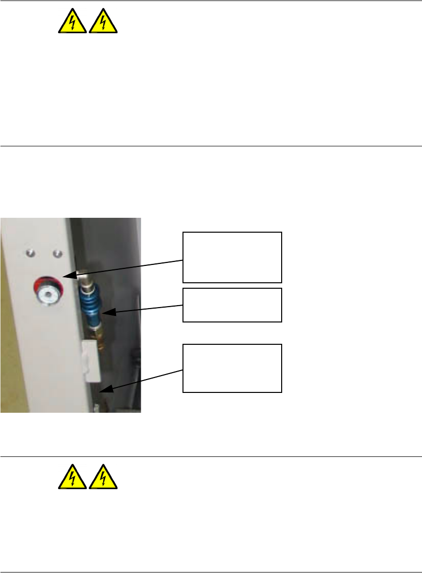
2.3.4 Cutting off the compressed air supply
Fig. 2 - 31 Filter regulator and hand sliding valve.
WARNING
Never loosen the compressed air connection before you are certain that the air pressure on the
filter regulator in the lift interior (accessible after opening the operator doors) and on the hand slid-
ing valve and the main valve on the air supply is turned off and the manometer on the Productivity
Lift reads 0 bar.
Manometer from the
filter regulator
Hand sliding valve
6bar compressed air
from main air supply

2 Operating safety User Manual - Productivity Lift
2.4 ESD regulations Edition 02/2004
38
2.4 ESD regulations
Comply to the instructions for the ESD regulations as are provided in the placement machine’s
user manual.
2.5 Fitting the transport locks
WARNING
The transport locks displayed as follows are a necessary safety mechanism for the machine.
When the lift is delivered, the vertical position of the "top conveyor" and the shuttle conveyor are
secured with the corresponding transport lock (see Fig. 2 - 32 und Fig. 2 - 33). The locks may only
be removed after the lift has been installed and directly before the unit is switched on for the first
time.
If a Productivity Lift which is to be relocated is presently installed in the line or to the SIPLACE
placement machine, then the transport locks must be fitted before the machine is moved as will
now be shown. Follow the instructions as described in the installation instructions for dismantling
and relocation of the lift. Before the Productivity Lift is switched back on, the transport locks must
be removed and fitted into the designated storage location in the interior of the lift. All tools must
also be removed from the lift area before the machine is first switched on.
Further information about the transport locks is available in the current installation instructions for
the Productivity Lift (Art.-Nr.00191967-02 / Edition 05/2004).