Productivity Lift.pdf - 第46页
2 Operating safety User Manual - Productivity Lift 2.4 ESD regulations Edition 02/2004 38 2.4 ESD regulations Comply to t he instructio ns for the ESD regulat ions as are provided in the place ment mach ine’s user manual…
User Manual - Productivity Lift 2 Operating safety
Edition 02/2004 2.3 Safety notices for the protection devices
37
2.3.3 Maintenance and cleaning
WARNING
If the Productivity Lift is to be cleaned or maintained, the transport locks must be fitted and the
compressed air must be switched off at the filter regulator as described in the sections 2.5 and
2.3.4.
the main switch must be correspondingly labelled and secured with a personal padlock so that the
machine cannot be unintentionally switched back on. The necessary work can now be carried out
by trained personnel using the instructions in the maintenance instructions.
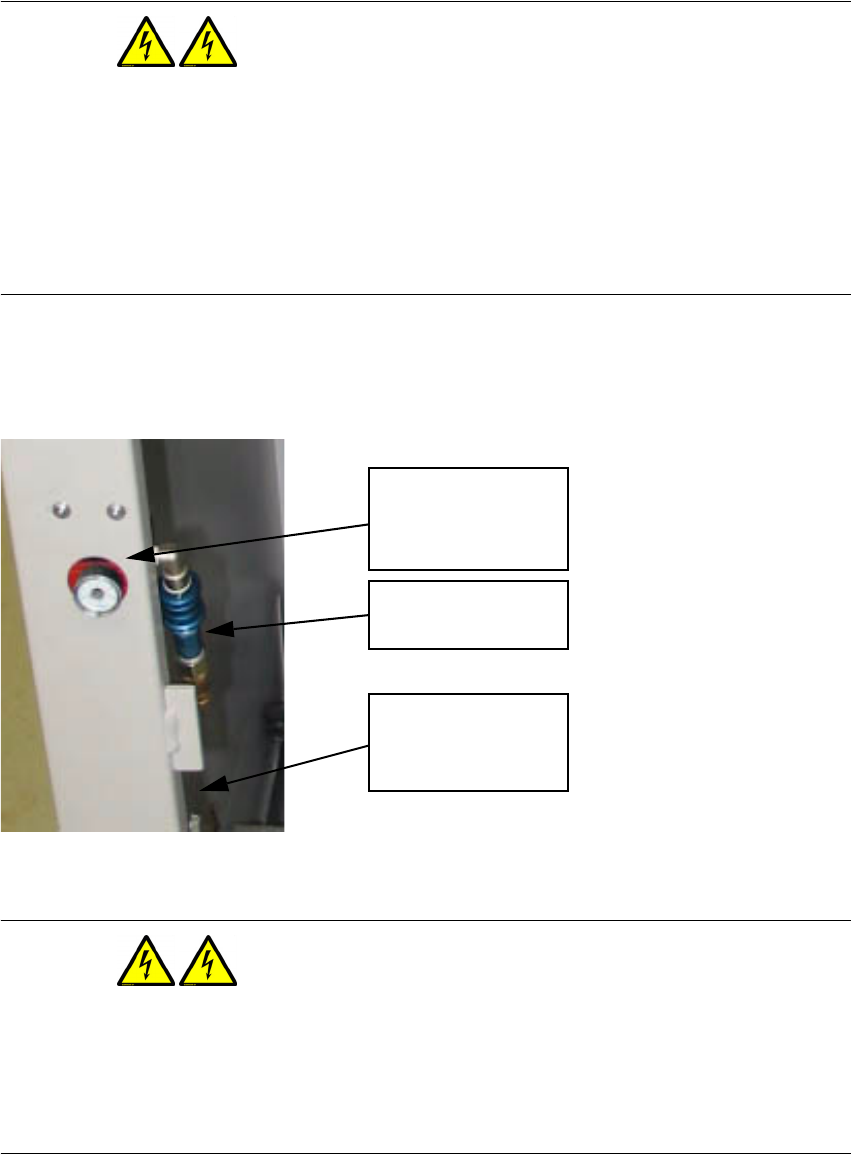
2.3.4 Cutting off the compressed air supply
Fig. 2 - 31 Filter regulator and hand sliding valve.
WARNING
Never loosen the compressed air connection before you are certain that the air pressure on the
filter regulator in the lift interior (accessible after opening the operator doors) and on the hand slid-
ing valve and the main valve on the air supply is turned off and the manometer on the Productivity
Lift reads 0 bar.
Manometer from the
filter regulator
Hand sliding valve
6bar compressed air
from main air supply

2 Operating safety User Manual - Productivity Lift
2.4 ESD regulations Edition 02/2004
38
2.4 ESD regulations
Comply to the instructions for the ESD regulations as are provided in the placement machine’s
user manual.
2.5 Fitting the transport locks
WARNING
The transport locks displayed as follows are a necessary safety mechanism for the machine.
When the lift is delivered, the vertical position of the "top conveyor" and the shuttle conveyor are
secured with the corresponding transport lock (see Fig. 2 - 32 und Fig. 2 - 33). The locks may only
be removed after the lift has been installed and directly before the unit is switched on for the first
time.
If a Productivity Lift which is to be relocated is presently installed in the line or to the SIPLACE
placement machine, then the transport locks must be fitted before the machine is moved as will
now be shown. Follow the instructions as described in the installation instructions for dismantling
and relocation of the lift. Before the Productivity Lift is switched back on, the transport locks must
be removed and fitted into the designated storage location in the interior of the lift. All tools must
also be removed from the lift area before the machine is first switched on.
Further information about the transport locks is available in the current installation instructions for
the Productivity Lift (Art.-Nr.00191967-02 / Edition 05/2004).
User Manual - Productivity Lift 2 Operating safety
Edition 02/2004 2.5 Fitting the transport locks
39
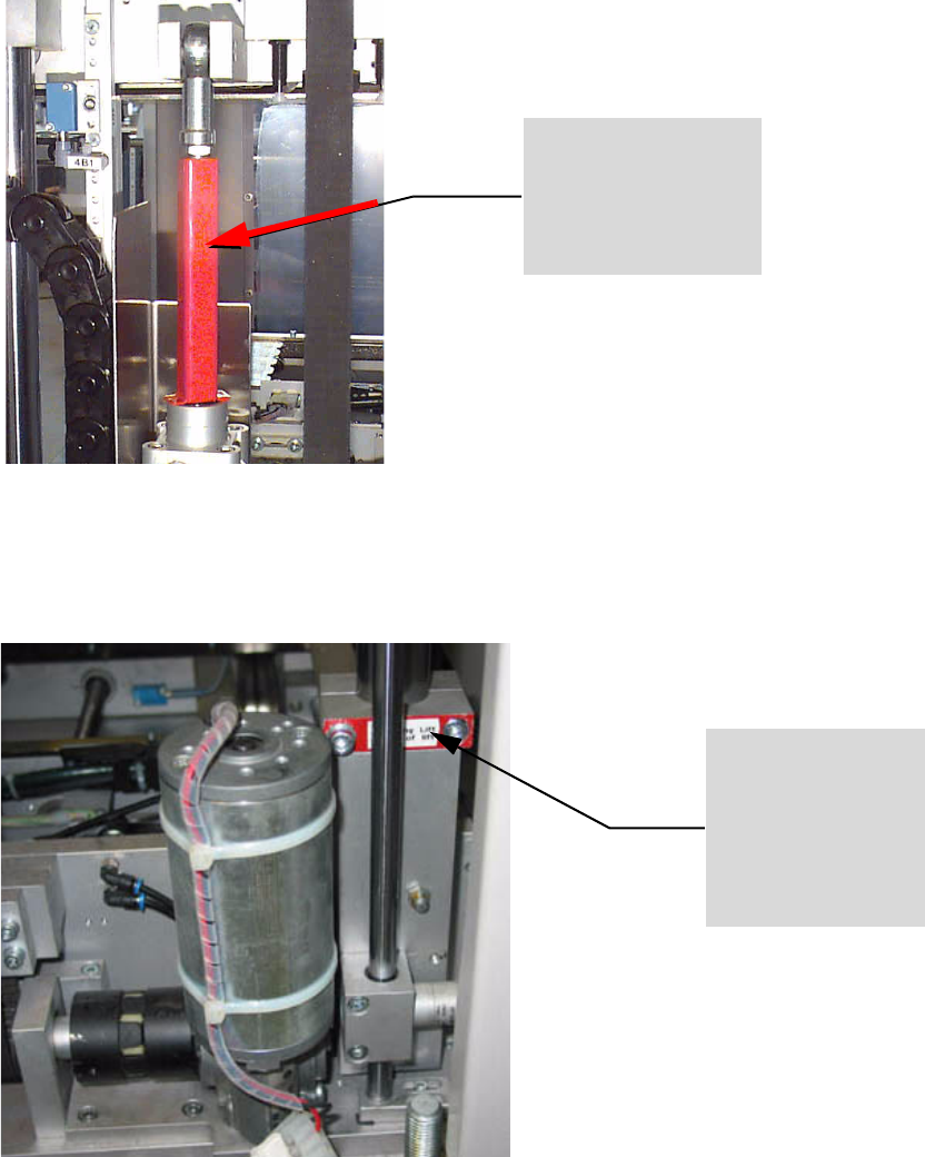
2.5.1 Fitting the transport locks for "top conveyor"
Fig. 2 - 32 Press transport lock U-rail onto the piston rod of „top conveyor“
2.5.2 Fitting the transport locks to the shuttle conveyor
Fig. 2 - 33 Fit the transport lock (clamping piece) from above against the shuttle conveyor
Locking of the „Top con-
veyor“ via transport lock
„U-rail“
BEFORE all intervention into the interior of the lift
and BEFORE relocation / transportation of the lift:
„top conveyor“ must be in the lowest posi-
tion.
Check the U-rail is securely fitted!
Locking of the Shuttle
Transport via transport
lock „clamping piece“.
BEFORE relocation/ transportation of
the lift unit:
Shuttle-conveyor must be DOWN:
Check the clamping piece is securely fit-
ted!