Productivity Lift.pdf - 第48页
2 Operating safety User Manual - Productivity Lift 2.6 Signal lamps Edition 02/2004 40 Fig. 2 - 34 Fit the transport lock (clamping pi ece) from belo w against the shuttle conveyor 2.6 Signal lamp s The machine is equipp…
User Manual - Productivity Lift 2 Operating safety
Edition 02/2004 2.5 Fitting the transport locks
39
2.5.1 Fitting the transport locks for "top conveyor"
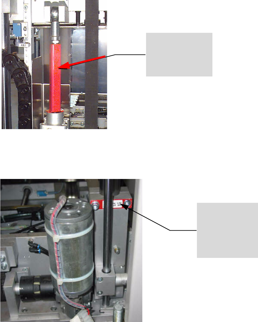
Fig. 2 - 32 Press transport lock U-rail onto the piston rod of „top conveyor“
2.5.2 Fitting the transport locks to the shuttle conveyor
Fig. 2 - 33 Fit the transport lock (clamping piece) from above against the shuttle conveyor
Locking of the „Top con-
veyor“ via transport lock
„U-rail“
BEFORE all intervention into the interior of the lift
and BEFORE relocation / transportation of the lift:
„top conveyor“ must be in the lowest posi-
tion.
Check the U-rail is securely fitted!
Locking of the Shuttle
Transport via transport
lock „clamping piece“.
BEFORE relocation/ transportation of
the lift unit:
Shuttle-conveyor must be DOWN:
Check the clamping piece is securely fit-
ted!
2 Operating safety User Manual - Productivity Lift
2.6 Signal lamps Edition 02/2004
40
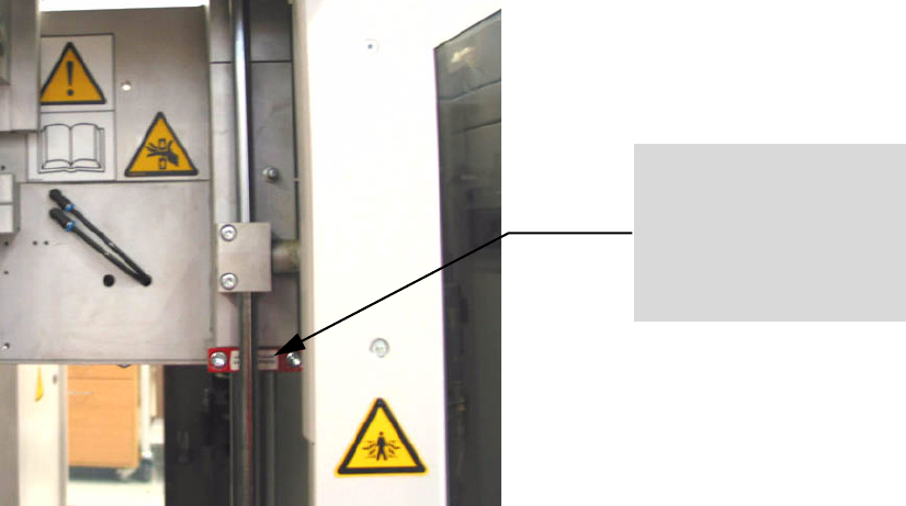
Fig. 2 - 34 Fit the transport lock (clamping piece) from below against the shuttle conveyor
2.6 Signal lamps
The machine is equipped with a green and a white signal lamp. The following functions are allo-
cated to the lamps:
Green - lit : Unit is running in automatic mode.
White - lit : Unit has an error
Locking of the Shuttle Trans-
port via mounting transport
lock „clamping piece“.
BEFORE all intervention into the lift inte-
rior, when the shuttle conveyor is up
Shuttle-conveyor in UPPER position:
Check the clamping piece is securely fit-
ted!

User Manual - Productivity Lift 3 Assembling and installing
Edition 02/2004 3.1 Installation and operating instructions
41
3 Assembling and installing
DANGER
The assembly and installation of the Productivity Lift (Lift unit and SPLC) may only be carried out
by service technicians from SIEMENS AG L&A or service technicians from the customer, who
have been trained and therefore authorised for these tasks at SIEMENS AG L&A.according to the
requirements in the Productivity Lift installation instructions (Article-No. 00191967-02 / Edition 05/
2004).
HINWEIS
The existing installation and maintenance manuals are valid for the installation of the unit and its
maintenance.
There are detailed instructions for transportation of the machine in the installation instructions.
3.1 Installation and operating instructions
For the installation and operating instructions please refer to the chapter 9.1 “Installation and op-
erating instructions” and 9.2 “Electrical and pneumatic connection”.
3.2 Switching the device on
Once the device has been switched on at the main switch, an emergency stop message appears
in the display, which must be confirmed using the "Enter" key. This will set the device to the stand-
by-operating mode.
Pressing the "Start" key sets the device to the automatic operating mode, which begins by running
an initialisation phase. This serves to test basic system functions.
Following this brief initialisation, the device is set to the automatic operating mode and is ready to
operate.