Productivity Lift.pdf - 第57页
User Manual - Productivity Lift Soko 00166631-01 / 12031477 5 Configuration Software version V 43.140 Edition April 2006 5.3 Interface 2 49 5.3 Interface 2 „Interface 2” define s the interf ace at th e outlet (n +1) to s…

5 Configuration User Manual - Productivity Lift Soko 00166631-01 / 12031477
5.2 Interface 1 Software version V 43.140 Edition April 2006
48
5.2 Interface 1
„Interface 1” defines the interface at the inlet (n-1) to previous systems.
The available settings are „SMEMA” and „Siemens”.
NOTE
The device is equipped with a defined interface. The interface shown in the display must conform
to the interface installed at the interface module AMI. It's possible to change the interface subse-
quently, but this may only be done by an authorised person.
Fig. 5 - 2 Interface 1
ALT
Enter
Start
Stop
Interface 1
Siemens
User Manual - Productivity Lift Soko 00166631-01 / 12031477 5 Configuration
Software version V 43.140 Edition April 2006 5.3 Interface 2
49
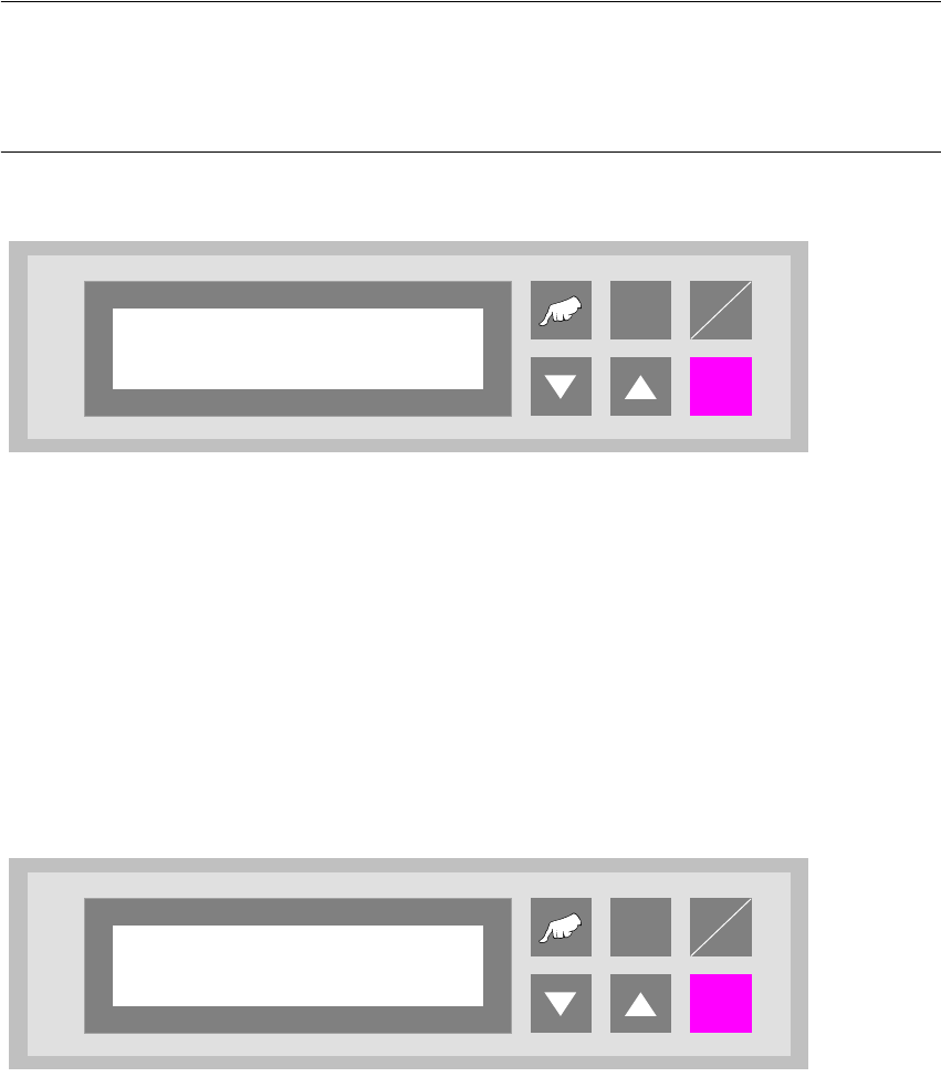
5.3 Interface 2
„Interface 2” defines the interface at the outlet (n+1) to subsequent systems.
The available settings are „SMEMA” and „Siemens”.
NOTE
The device is equipped with a defined interface. The interface shown in the display must conform
to the interface installed at the interface module AMI. It is possible to change the interface subse-
quently, but this may only be done by an authorised person.
Fig. 5 - 3 Interface 2
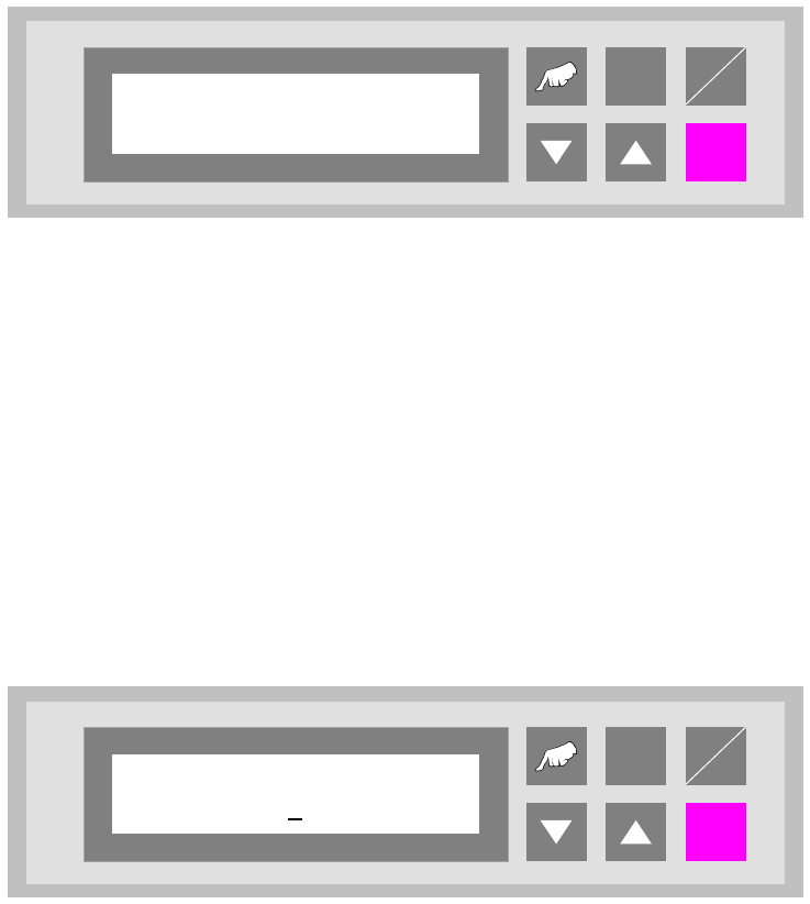
5.4 Wait period PCB
Time buffer for transferring a printed circuit board. Once this period has elapsed, the belt drive is
switched off and a fault indication is output since no PCB has arrived at the light barrier.
The unit of value is [0.01s] and the setting range is between 300 and 9999, which corresponds to
a time of 3 s to 99.99 s.
Fig. 5 - 4 Wait period PCB
ALT
Enter
Start
Stop
Interface 2
Siemens
ALT
Enter
Start
Stop
Wait period PCB
2000
5 Configuration User Manual - Productivity Lift Soko 00166631-01 / 12031477
5.5 Wait time track 2 Software version V 43.140 Edition April 2006
50
5.5 Wait time track 2
This function is to try to ensure that both tracks are occupied so that 2 PCBs can be transferred
simultaneously to the pick and place machine.
Since the PCBs arrive at different times, then a wait time is set in this menu which begins on arrival
of the first PCB. If the second PCB does not arrive on the other track before this time has elapsed,
then the first PCB is handed over alone to the pick and place machine.
If the wait time is set to „0“ the PCB which arrives first will be immediately handed over to the pick
and place machine.
1 unit has a value of [0,01s] and can be set within the range 0 to 9999.
Fig. 5 - 5 Wait time track 2
5.6 Max. time un-belt
If a PCB has not been transferred from the conveyor to the lift after the adjusted time, the auto-
matic operating mode is stopped and the error signal shows „PCB annuated”. The PCB is only
then transferred from the conveyor to the following lift when the error signal is confirmed with the
„Enter” cursor through the user.
The unit of the value is [s] and the adjustment area is 0s to 9999s, whereas the function is switched
off for the value 0s.
Fig. 5 - 6 Max. time un-belt
ALT
Enter
Start
Stop
Wait time track 2
1000
ALT
Enter
Start
Stop
Max. time un-belt
0